


Create successful ePaper yourself
Turn your PDF publications into a flip-book with our unique Google optimized e-Paper software.
Field Testing and Instrumentation <strong>of</strong> <strong>Railway</strong> <strong>Vehicle</strong>s 425<br />
dynamics model. In any case, simulation <strong>of</strong> these tests forms a common part <strong>of</strong> vehicle<br />
development to ensure that proposed designs meet the required standards. As such tests will be<br />
carried out on all vehicles accepted for service, they may also provide a useful source <strong>of</strong><br />
information to validate models <strong>of</strong> existing vehicles.<br />
In addition, the dynamics engineers may also be involved with testing to assess performance<br />
against specified criteriasuch as passenger comfort or to investigate problems with existing rolling<br />
stock.<br />
Reproducing track geometry —many simulation tasks will require the use <strong>of</strong> “real” track<br />
geometry measured by ahigh-speed recording vehicle or hand operated trolleys. Although such<br />
data is generally presented as “ready to use,” experience has shown that an appreciation <strong>of</strong> the<br />
measuring systems and instrumentation used is vital to ensurethat an accurate reconstruction<strong>of</strong>the<br />
track geometry can be obtained.<br />
Measuring wheel and rail pr<strong>of</strong>iles —accurate representations <strong>of</strong> worn wheel and rail pr<strong>of</strong>iles<br />
are vital to understanding vehicle (and track) behaviour. Anumber <strong>of</strong> proprietary devices are<br />
available to measurepr<strong>of</strong>iles, however,aswith track geometry, accurateresults will be aidedbyan<br />
understanding <strong>of</strong> the principles behind their operation.<br />
II. COMMON TRANSDUCERS<br />
This section provides abrief overview <strong>of</strong> the range <strong>of</strong> transducers commonly encountered to<br />
measure displacement, acceleration, and force.<br />
A. D ISPLACEMENT T RANSDUCERS<br />
These are used for measuring linear or rotational displacements. The most common type <strong>of</strong><br />
transducer is the linear variabledifferential transformer (LVDT). This comprises atransformer with<br />
asingle primary coil and two secondary coils wound onto ahollow cylindrical tube as shown in<br />
Figure 13.1.Within this tube, aferromagnetic core can move up and down.The primary coil at the<br />
centre <strong>of</strong> the tube is excited with an AC signal and this induces avoltage in the secondary coils.<br />
The secondary coils are normally connected asshown in Figure 13.2. This arrangement, known as<br />
“series opposition,” 3 has the effect <strong>of</strong> producing zero output voltage with the core in its central or<br />
zero position. As the core is moved, the coupling between the primary and one <strong>of</strong> the secondary<br />
coils increases whilst the coupling with the other secondary coil decreases in direct proportion.<br />
With correct arrangement <strong>of</strong>the coils and core, the resulting output voltage will be linear over the<br />
majority <strong>of</strong> the stroke. It should be noted that as the core moves past the zero position(central on the<br />
primary coil), the output voltage undergoes a1808 phase shift.<br />
In practice, atransducer that requires ACinput and produces AC output is inconvenient, so a<br />
signal processing module is used in conjunction with the LVDT. This senses the zero-passingphase<br />
shift described above and uses this to distinguish between AC signals <strong>of</strong> equal amplitudeeither side<br />
<strong>of</strong> the zero position. The resulting conditioned outputistherefore apositive or negativeDCvoltage<br />
either side <strong>of</strong> the zero position. The signal conditioning module usually also converts aDCsupply<br />
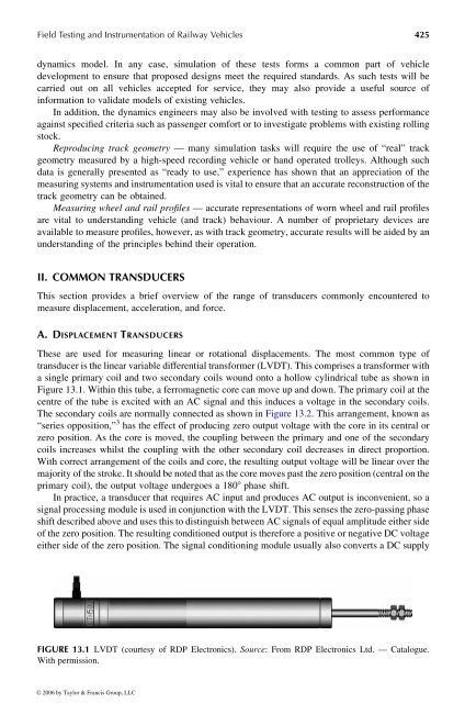
FIGURE 13.1 LVDT (courtesy <strong>of</strong> RDP Electronics). Source: From RDP Electronics Ltd. —Catalogue.<br />
With permission.<br />
© 2006 by Taylor & Francis Group, LLC


