


Create successful ePaper yourself
Turn your PDF publications into a flip-book with our unique Google optimized e-Paper software.
452<br />
<strong>of</strong> measuring wheels so that abetter reference line can be used. However, this <strong>of</strong>fsets the essential<br />
benefit <strong>of</strong> this method, namely its simplicity.<br />
Chord <strong>of</strong>fset based measuring vehicles are no longer incommon usage and data measured by<br />
such systems should betreated with some caution by the dynamics engineer for the reasons<br />
discussed.<br />
VII. EXAMPLES OF VEHICLE LABORATORY AND FIELD TESTS<br />
This sectionprovide examples <strong>of</strong> laboratory andfieldtests that maybecommonlyencountered by,or<br />
provide useful information for, the vehicle dynamics engineer. Whilst they are based specifically on<br />
U.K. practice, similar tests are employed bymany railway administrations worldwide.<br />
A. S TATIC/QUASI- S TATIC T ESTS<br />
These tests are normally carriedout on avehicle in aspecialist laboratory. Theresults may be used<br />
to gain confidence in the general behaviour <strong>of</strong> avehicle model and also to estimate the additional<br />
(parasitic) stiffness present in the completed vehicle. However, as the dynamic behaviour can vary<br />
considerably from the static behaviour, some comparisons against dynamics tests (such as ride<br />
tests) are required toenable avehicle model to be fully validated.<br />
1. Wheel Unloading Test<br />
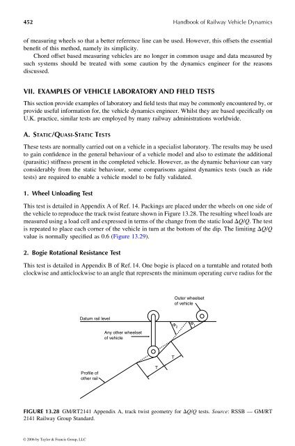
This testisdetailed in Appendix A<strong>of</strong>Ref. 14.Packings are placed under the wheels on one side <strong>of</strong><br />
the vehicle to reproduce the track twist featureshown in Figure 13.28.The resulting wheel loads are<br />
measured usingaload cell and expressedinterms <strong>of</strong> the change from the static load D Q / Q .The test<br />
is repeated to place each corner <strong>of</strong>the vehicle in turn at the bottom <strong>of</strong> the dip. The limiting D Q / Q<br />
value isnormally specified as 0.6 (Figure 13.29).<br />
2. Bogie Rotational Resistance Test<br />
This test is detailed in Appendix B<strong>of</strong>Ref. 14. One bogie is placed on aturntable and rotated both<br />
clockwise and anticlockwise to an anglethat represents the minimum operating curve radius for the<br />
Datum rail level<br />
Pr<strong>of</strong>ile <strong>of</strong><br />
other rail<br />
Any other wheelset<br />
<strong>of</strong> vehicle<br />
Outer wheelset<br />
<strong>of</strong> vehicle<br />
FIGURE 13.28 GM/RT2141 Appendix A, track twist geometry for D Q / Q tests. Source: RSSB —GM/RT<br />
2141 <strong>Railway</strong> Group Standard.<br />
© 2006 by Taylor & Francis Group, LLC<br />
T<br />
Φ 2<br />
T<br />
<strong>Handbook</strong> <strong>of</strong> <strong>Railway</strong> <strong>Vehicle</strong> <strong>Dynamics</strong><br />
Φ 1


