


You also want an ePaper? Increase the reach of your titles
YUMPU automatically turns print PDFs into web optimized ePapers that Google loves.
436<br />
AB C D E F<br />
Q 1<br />
X 1<br />
Y 1<br />
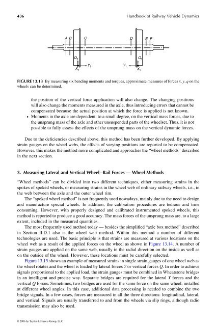
FIGURE 13.13 By measuring six bending moments and torques, approximate measures <strong>of</strong> forces x , y , q on the<br />
wheels can be determined.<br />
the position <strong>of</strong> the vertical force application will also change. The changing positions<br />
will also change the momentsmeasured in the axle, thus introducingerrors that cannot be<br />
compensated because the actual position at which the force is applied is not known.<br />
† Moments in the axle are dependent, to asmall degree, on the vertical mass forces, due to<br />
the unsprung mass<strong>of</strong>the axle and otherunsuspended parts <strong>of</strong> the wheelset. Thus, it is not<br />
possible to fully assess the effects <strong>of</strong> the unsprung mass on the vertical dynamic forces.<br />
Due to the deficiencies described above, this method has been further developed. Byapplying<br />
strain gauges on the wheel webs, the effects <strong>of</strong> varying positions are reported to be compensated.<br />
However, this makes the method morecomplicated and approaches the “wheel methods” described<br />
in the next section.<br />
3. Measuring Lateral and Vertical Wheel–Rail Forces —Wheel Methods<br />
“Wheel methods” can be divided into two different techniques, either measuring strains in the<br />
spokes <strong>of</strong> spoked wheels, or measuring strains in the wheel web <strong>of</strong> ordinaryrailway wheels,i.e., in<br />
the web between the axle and the outer wheel rim.<br />
The“spokedwheel method” is notfrequently used nowadays, mainlydue to the need to design<br />
and manufacture special wheels. In addition, the calibration procedures are tedious and time<br />
consuming. However, with properly designed and calibrated instrumented spoked wheels, this<br />
method is reportedtoproduceagood accuracy. The massforces <strong>of</strong> the unsprung mass are, to alarge<br />
extent, included inthe measured quantities.<br />
Themostfrequently used method today —besides the simplified“axle box method” described<br />
in Section II.D.1 also is the wheel web method. Within this method a number <strong>of</strong> different<br />
technologies are used. The basic principle is that strains are measured at various locations on the<br />
wheel web as aresult <strong>of</strong> the applied forces on the wheel as shown inFigure 13.14. Anumber <strong>of</strong><br />
strain gauges are applied on the same web, usually in the radial direction on the inside as well as<br />
on the outside <strong>of</strong> the wheel. However, these locations must be carefully selected.<br />
Figure13.15 showsanexample<strong>of</strong>measured strains in single strain gauges <strong>of</strong> onewheel web as<br />
the wheel rotates and the wheel is loaded by lateral forces Y or vertical forces Q .Inorder to achieve<br />
signals proportional to the applied load,the strain gauges mustbecombined in Wheatstone bridges<br />
in an intelligent and precise way. Separate bridges are required for the lateral Y forces and the<br />
vertical Q forces. Sometimes, two bridges are used for the sameforce onthe same wheel, installed<br />
at different wheel angles. In this case, additional data processing is needed tocombine the two<br />
bridge signals. In afew cases, forces are measured in all the three directions: longitudinal, lateral,<br />
and vertical. Signals are usually transferred to and from the wheels via slip rings, although radio<br />
transmission may also beused.<br />
© 2006 by Taylor & Francis Group, LLC<br />
Y 1<br />
<strong>Handbook</strong> <strong>of</strong> <strong>Railway</strong> <strong>Vehicle</strong> <strong>Dynamics</strong><br />
Q 1<br />
X 1


