


Create successful ePaper yourself
Turn your PDF publications into a flip-book with our unique Google optimized e-Paper software.
Field Testing and Instrumentation <strong>of</strong> <strong>Railway</strong> <strong>Vehicle</strong>s 453<br />
FIGURE 13.29 Wheel unloading test.<br />
vehicle. The test is usually performed at 0.2 and 1 8 /sec rotation speeds and the torque required to<br />
rotate the bogie is measured (Figure 13.30). Where yaw dampers are fitted, they may or may not be<br />
disconnected during the test depending on the test requirements. If yaw dampers with positional<br />
control (i.e., designed to blow-<strong>of</strong>fataparticular bogie rotation angle) are included, the results from<br />
the test will reflect both the velocity and displacement dependent nature <strong>of</strong> such an arrangement.<br />
It follows that the vehicle modelmust be simulated in the same condition if comparable results are<br />
to be achieved. The resulting X -factor is calculated as follows:<br />
X ¼<br />
Body to bogie yaw torque<br />
Wheelbase x axleload<br />
The limiting value is 0.1 except for freight vehicles , 8tonnes axle load.<br />
The measured bogie rotation torques are particularly useful when confirming the behaviour <strong>of</strong><br />
avehicle model with friction sidebearers or airspring secondary suspensions. Typical examples<br />
<strong>of</strong> results from such tests for various vehicles are shown inFigure 13.31.<br />
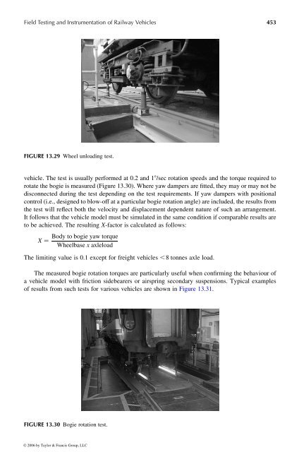
FIGURE 13.30 Bogie rotation test.<br />
© 2006 by Taylor & Francis Group, LLC


