


You also want an ePaper? Increase the reach of your titles
YUMPU automatically turns print PDFs into web optimized ePapers that Google loves.
444<br />
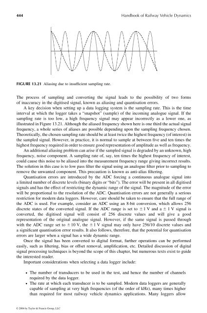
FIGURE 13.21 Aliasing due to insufficient sampling rate.<br />
<strong>Handbook</strong> <strong>of</strong> <strong>Railway</strong> <strong>Vehicle</strong> <strong>Dynamics</strong><br />
The process <strong>of</strong> sampling and converting the signal leads to the possibility <strong>of</strong> two forms<br />
<strong>of</strong> inaccuracy in the digitised signal, known as aliasing and quantisation errors.<br />
Akey decision when setting up adata logging system is the sampling rate. This is the time<br />
interval at which the logger takes a“snapshot” (sample) <strong>of</strong> the incoming analogue signal. If the<br />
sampling rate is too low, ahigh frequency signal may appear incorrectly as alower one, as<br />
illustrated in Figure 13.21.Although the aliasedfrequencyshownhere is one third the actual signal<br />
frequency, awhole series <strong>of</strong> aliases are possible depending upon the sampling frequency chosen.<br />
Theoretically,the chosen sampling rate should be at least twice the highest frequency(<strong>of</strong> interest) in<br />
the sampled signal. However, in practice, it is normal to sample at between five and ten times the<br />
highest frequencyrequiredinorder to ensuregood representation <strong>of</strong> amplitudeaswell as frequency.<br />
An additional aliasing problem can arise if the sampledsignal is degraded by an unknown, high<br />
frequency, noise component. Asampling rate <strong>of</strong>, say, ten times the highest frequency <strong>of</strong>interest,<br />
could cause this noise to be aliased into the measurement frequency range giving incorrect results.<br />
The solution in this case is to low pass filter the signal using ananalogue filter prior to sampling to<br />
remove the unwanted component. This precaution is known asanti-alias filtering.<br />
Quantisation errors are introduced by the ADC forcing acontinuous analogue signal into<br />
alimited number <strong>of</strong> discrete levels (binary digits or “bits”). The error will be present in all digitised<br />
signals and has the effect <strong>of</strong> restrictingthe dynamic range <strong>of</strong> the signal. Themagnitude <strong>of</strong> the error<br />
will be proportional tothe resolution <strong>of</strong>the ADC. Quantisation errors are not generally aserious<br />
restriction for modern data loggers. However, care should betaken to ensure that the full range <strong>of</strong><br />
the ADC is used. For example, consider an ADC using an 8-bit conversion, which allows 256<br />
discrete states <strong>of</strong> the converted signal. If the ADC range is set to ^ 1V and a ^ 1V signal is<br />
converted, the digitised signal will consist <strong>of</strong> 256 discrete values and will give a good<br />
representation <strong>of</strong> the original analogue signal. However, if the same signal is passed through<br />
with the ADC range set to ^ 10 V, the ^ 1Vsignal may only have 256/10 discrete values and<br />
asignificant quantisation error results. It also follows, therefore, that the potential for quantisation<br />
errors are larger when asignal has awide dynamic range.<br />
Once the signal has been converted todigital format, further operations can be performed<br />
easily, such as filtering, bias or <strong>of</strong>fset removal, amplification, etc. Detailed discussion <strong>of</strong> digital<br />
signal processing techniques is beyond the scope <strong>of</strong> this chapter, but numerous texts exist toguide<br />
the interested reader.<br />
Important considerations when selecting adata logger include:<br />
† The number <strong>of</strong> transducers to be used in the test, and hence the number <strong>of</strong> channels<br />
required by the data logger.<br />
† The rate at which each transducer is to be sampled. Modern data loggers are generally<br />
capable <strong>of</strong> sampling at very high frequencies (<strong>of</strong> the order <strong>of</strong> kHz), many times higher<br />
than required for most railway vehicle dynamics applications. Many loggers allow<br />
© 2006 by Taylor & Francis Group, LLC


