- Page 1 and 2:
Wile,.· Interactenee ..A. .. 1 18
- Page 3 and 4:
Circuit Design U sing Personal Comp
- Page 5 and 6:
To my late parents, Tommy and Brown
- Page 7 and 8:
viii Preface computer. Excessive th
- Page 9 and 10:
Contents l. Introduction 1 2. Some
- Page 11 and 12:
Contetlts xiii 4.3.4. Transmission
- Page 13 and 14:
~----- ---- Contents xv 6.6. Pseudo
- Page 15 and 16:
-------------------------- Contents
- Page 17 and 18:
-- ------- 2 Introduction viewpoint
- Page 19 and 20:
4 Introduction Chapters Four and Fi
- Page 21 and 22:
6 Introduction the selectivity effe
- Page 23 and 24:
8 Some Fundamenurl Numerical Method
- Page 25 and 26:
10 Some Fundamental Numerical Metho
- Page 28 and 29:
--------------------- Romberg Integ
- Page 30 and 31:
and it is convenient to rearrange (
- Page 32 and 33:
Romberg Integranon 17 Truncation Er
- Page 34 and 35:
---~-- - - -- ----- - -------------
- Page 36 and 37:
Polynomial Minimox Approximation of
- Page 38 and 39:
Polynomial Minimax Approximation of
- Page 40 and 41:
Rational Polynomial LSE Approximati
- Page 42 and 43:
---~~--_._--- ------ ID(w)£(w)1 2
- Page 44 and 45:
Rational Polynomial LSE Approximati
- Page 46 and 47:
Problems 31 2.6. If a,Z+a2 w = -a'-
- Page 48 and 49:
sense by the sum of first-kind Cheb
- Page 50 and 51:
Complex Zeros of Complex Polynomial
- Page 52 and 53:
Complex Zeros ofComplex Polynomials
- Page 54 and 55:
which are equal to the polynomial C
- Page 56 and 57:
Complex Zeros of Complex Polynomial
- Page 58 and 59:
Table 3.3. Complex Zeros of Complex
- Page 60 and 61:
Polynomials From Complex Zeros and
- Page 62 and 63:
Polynomials From Complex Zeros and
- Page 64 and 65:
Polynomial Addition and Subtraction
- Page 66 and 67:
Continued Fraction Expansion 51 Not
- Page 68 and 69:
Case 1 (row ~t (al N" 3 -1 '" 25 +
- Page 70 and 71:
---- ------------------------- Cont
- Page 72 and 73:
----~------- Input ImpedafJce $ytrt
- Page 74 and 75:
Input Impedance Synthesis From Its
- Page 76 and 77:
------- - ------------- ---- Input
- Page 78 and 79:
Long Division and Partial Fraction
- Page 80 and 81:
Problems 6S magnitude. The program
- Page 82 and 83:
- Problems 67 3.12. Given the resis
- Page 84 and 85:
.Chapter Four Ladder Network Analys
- Page 86 and 87:
- -- - -------- Recun;"" ludder Met
- Page 88 and 89:
Recursive Ladder Method 73 This alw
- Page 90 and 91:
--------------- Example a: 3,325,20
- Page 92 and 93:
Recursive Ladder Method 77 This las
- Page 94 and 95:
- - - -------------- Embedded T>vo-
- Page 96 and 97:
- - - - - --- - - - ---- Unifonn Tr
- Page 98 and 99:
--- - .._----- Unifonn T/'Qnsmissio
- Page 100 and 101:
--------------- Uniform Transmissio
- Page 102 and 103:
------- --- -----------_. - ------
- Page 104 and 105:
Table 4.4. 6.d L1 6.dc, 6.d L2 6.d
- Page 106 and 107:
------- - _. - - Input and Transfer
- Page 108 and 109:
Input and Transfer Network Response
- Page 110 and 111:
Input and Transfer Network Response
- Page 112 and 113:
----------------------------- Time
- Page 114 and 115:
----- - - h(-rJ h(2.6.Tl o I II ---
- Page 116 and 117:
-------- Sensitivities 101 the corr
- Page 118 and 119:
formula: Sensitivities 103 dZ""A,Z
- Page 120 and 121:
Sensitivities 105 obeying at least
- Page 122 and 123:
and its derivative with respect to
- Page 124 and 125:
Problems 109 branch immittance; the
- Page 126 and 127:
Problems 111 Solve by using (4.40)
- Page 128 and 129:
Chapter Five Gradient Optimization
- Page 130 and 131:
Gradient Optimization 115 Figure 5.
- Page 132 and 133:
-- ------------------ Quadratic Fon
- Page 134 and 135:
Quadratic Fonns and Ellipsoids 119
- Page 136 and 137:
Quadratic Forms and EUipsoids 121 F
- Page 138 and 139:
Quadratic Fonm and Ellipsoids 123 x
- Page 140 and 141:
Quadratic Forms and Ellipsoids 115
- Page 142 and 143:
Conjugate Gradient Search 127 choic
- Page 144 and 145:
-_.. ---------- Conjugate Gradient
- Page 146 and 147:
Conjugate Gradient Search 131 x, Fi
- Page 148 and 149:
-- -~--- Conjugate Gradient Search
- Page 150 and 151:
Conjugate Gradient Search 135 Hxl =
- Page 152 and 153: Linear Search 137 the variable metr
- Page 154 and 155: Then, the minimum function value in
- Page 156 and 157: - ------- Linear Search 141 subtrac
- Page 158 and 159: The F/etcher- Reeves Optimizer 143
- Page 160 and 161: The netcher- Reeves Optimizer 145 c
- Page 162 and 163: Table 5.4. Typical Output for the R
- Page 164 and 165: The Fletcher- Reeves Optimizer 149
- Page 166 and 167: Network Objective Functions 151 and
- Page 168 and 169: -------- - - Network Objecti"" Func
- Page 170 and 171: Network Objective Functions 155 Tab
- Page 172 and 173: -- ------------ Constraints 157 tra
- Page 174 and 175: - - - - - -------------- Constraint
- Page 176 and 177: Table 5.7. Objective Subroutine lor
- Page 178 and 179: -70. Constrainis 163 315-325). For
- Page 180 and 181: Constraints 165 In fact, one applic
- Page 182 and 183: --------~ - - ---------------------
- Page 184 and 185: (b) Problems 169 Find the diagonal
- Page 186 and 187: Impedance Matching 171 I, z, ---+__
- Page 188 and 189: Narrow·Band L, T, and Pi Networks
- Page 190 and 191: - - - --------------- + '" R, . " N
- Page 192 and 193: NalTO...Band L, T, and Pi Networks
- Page 194 and 195: Narrow-Bond L, T, and Pi Networks ]
- Page 196 and 197: Narrow-BaruJ L, T, aruJ Pi Networks
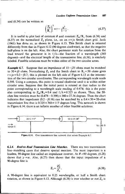
- Page 198 and 199: Loss/ess Unifonn Transmission Lines
- Page 200 and 201: ------- - -------------------------
- Page 204 and 205: Fano's Broodband-Matching Limitatio
- Page 206 and 207: Fano's Broadband-Matching Limitatio
- Page 208 and 209: ----------------- Fano's Broadband-
- Page 210 and 211: Fano's Broadband-Matching Limitatio
- Page 212 and 213: Fano's Broadband-Matching Limitatio
- Page 214 and 215: Fono's Broadband·Matching Limitati
- Page 216 and 217: Green's recursive element formula i
- Page 218 and 219: f 9, Figure 6.24. 92
- Page 220 and 221: Bandpass Network Transformations 20
- Page 222 and 223: Bandpass Network Trans/onnotions 20
- Page 224 and 225: 50 II 2.6548 16.594 Bandpass Networ
- Page 226 and 227: BaruJpass Network TransJof1lUltions
- Page 228 and 229: Pseudobandpass Matching Networks 21
- Page 230 and 231: I InlPJ =In Pseudobandpass Matching
- Page 232 and 233: Pseudobandpass Matching Networks 21
- Page 234 and 235: ----- -- Carlin's Broodband-Matchin
- Page 236 and 237: ---- -------------------- expressio
- Page 238 and 239: Car/in's Broadband.Matching Method
- Page 240 and 241: Carlin's Broadband-Matching Methad
- Page 242 and 243: Prohle"" 227 Third, an objective fu
- Page 244 and 245: Problems 229 6.16. Program Equation
- Page 246 and 247: Bilinear Tronsfonnatl'ons 231 I, ~-
- Page 248 and 249: Bi/inear Transjormations 233 (w" w"
- Page 250 and 251: Bilinear Transfonnations 235 accomp
- Page 252 and 253:
Bilinear Transfonnations 237 circle
- Page 254 and 255:
Impedance Mapping 239 1 3 al~ ~a3 [
- Page 256 and 257:
Impedance Mapping 241 r-- Z, s" I,
- Page 258 and 259:
---------- Impedan£e Mapping 243 T
- Page 260 and 261:
Impedance Mapping 245 in Figure 7.7
- Page 262 and 263:
Two-Port Impedance and Power Models
- Page 264 and 265:
---------------- This may be put in
- Page 266 and 267:
----~-------~--- - - --------------
- Page 268 and 269:
-------- -- - -------------- and th
- Page 270 and 271:
Two-Port Impedance and Power Models
- Page 272 and 273:
Billlteral Scattering Stability and
- Page 274 and 275:
Bilateral Scattering Stability and
- Page 276 and 277:
Bilateral Scattering Stability and
- Page 278 and 279:
Bilateral Scattering Stability and
- Page 280 and 281:
--- -------- Bilateral Scattering S
- Page 282 and 283:
Unilateral Scattering Gain 267 the
- Page 284 and 285:
Unilateral Scattering Gain 269 The
- Page 286 and 287:
Prohle"" 271 _merit is u=0.08; by (
- Page 288 and 289:
Chapter Eight Direct-Coupled Filter
- Page 290 and 291:
- -- ~-------~- -------------- Dire
- Page 292 and 293:
Prototype Network 277 and Wo is the
- Page 294 and 295:
Prototype Network 279 element value
- Page 296 and 297:
Prototype Network 281 8./.4. Protot
- Page 298 and 299:
Designing with Lande Inverters 283
- Page 300 and 301:
Designing with L and C Inverters 28
- Page 302 and 303:
Designilrg with Lande Inverters Sup
- Page 304 and 305:
Designing with L and C Inverters 28
- Page 306 and 307:
General Inverters, Resonators, and
- Page 308 and 309:
General Inverters, Resonators, and
- Page 310 and 311:
Genera/Inverters, Resonators, and E
- Page 312 and 313:
conductance of the Kth resonator is
- Page 314 and 315:
General Inverters, Resonators, and
- Page 316 and 317:
Table 8.2. General Inverters, Reson
- Page 318 and 319:
General Inveners, Resonators, and E
- Page 320 and 321:
Four Importunt Pussband Shapes 305
- Page 322 and 323:
Four Important Passband Shapes 307
- Page 324 and 325:
FOIl' Important Possband Shopes 309
- Page 326 and 327:
Four Important Passband Shapes 311
- Page 328 and 329:
Four Important Passband Shapes 313
- Page 330 and 331:
Four Important Passband Shapes 315
- Page 332 and 333:
Fou, Important Passband Shapes 317
- Page 334 and 335:
Four lmporlunt Pussband Shupes 319
- Page 336 and 337:
Comments on a Design Procedure 321
- Page 338 and 339:
Comments on a Design Procedure 323
- Page 340 and 341:
Comments on a Design Procedure 325
- Page 342 and 343:
-----~------------ A Complete Desig
- Page 344 and 345:
A Complete Design Example 329 DB3 =
- Page 346 and 347:
A Complete Design Example 331 R,,(l
- Page 348 and 349:
------- Problems 333 For Z=O+jX, fi
- Page 350 and 351:
------------- Chapter Nine Other Di
- Page 352 and 353:
, I II r L;.. I I . C, ~ ~ Wo ell :
- Page 354 and 355:
• e/2 e/2 Figure 9.3. A typical e
- Page 356 and 357:
Another trigonometric identity can
- Page 358 and 359:
o---iS~-----, I '--------;::==-----
- Page 360 and 361:
Introduction to Cauer Elliptic Filt
- Page 362 and 363:
Introduction to Cauer Elliptic Filt
- Page 364 and 365:
40 20 140 12 11 130 10 120 110 9 10
- Page 366 and 367:
00 Introduction to Cauer Elliptic F
- Page 368 and 369:
Doubly Termi/lllted Elliptic Filter
- Page 370 and 371:
Doubly TermillQted Elliptic Filters
- Page 372 and 373:
Doubly Terminated Elliptic Filters
- Page 374 and 375:
Doubly Terminated Elliptic FilteN 3
- Page 376 and 377:
Doubly TerrnilUlted Elliptic Filten
- Page 378 and 379:
Some Lumped.Element Transformations
- Page 380 and 381:
-lin '" 1 +jOn : c, 3L, L, I ) r So
- Page 382 and 383:
1 1CT (T Some Lumped.Element Tronsj
- Page 384 and 385:
Load Effects on Passive Networks 36
- Page 386 and 387:
Load Effects on Passive Networks 37
- Page 388 and 389:
Load Effects on Passive Networks 37
- Page 390 and 391:
Load Effects on Passive Networks 37
- Page 392 and 393:
Invulnerable Filters 377 9.6. Invul
- Page 394 and 395:
Invulnerable Filters 379 20 t lmin
- Page 396 and 397:
Invulnerable Filters 381 40 t L mil
- Page 398 and 399:
Problems. 383' corresponding number
- Page 400 and 401:
Problems 385 9.11. A passive networ
- Page 402 and 403:
Program AS-I. Swain's Snrface See E
- Page 404 and 405:
------- -------- - _. _. - Program
- Page 406 and 407:
----- _. - ------------- - Program
- Page 408 and 409:
- - - _._------------------ &61 TAN
- Page 410 and 411:
Program A6-4. Norton Transformation
- Page 412 and 413:
861 862 863 86' 865 866 B6? 868 869
- Page 414 and 415:
Program A7·2. Three-Port to Two·P
- Page 416 and 417:
15B .LBU Cue & 5to 3x3 Elements J5J
- Page 418 and 419:
e61 STOB 32 degrees 115 RCL9 a3 deg
- Page 420 and 421:
Program A7-4. Maximally Efficient G
- Page 422 and 423:
169 CHS Register Assignments: 17e e
- Page 424 and 425:
84e 841 842 843 844 845 846 847 848
- Page 426 and 427:
Program A8-2. Doubly Termiuated Min
- Page 428 and 429:
----- - - - _. - _.--------- - -- _
- Page 430 and 431:
-------_._--- ------- Program A9-1.
- Page 432 and 433:
Appendix B PET BASIC Programs Progr
- Page 434 and 435:
Program B2-2A. Gauss-Jordan Solutio
- Page 436 and 437:
- - -------------------------------
- Page 438 and 439:
Program B2-4B. Polynomial Minimax A
- Page 440 and 441:
Program B2-5. Levy's Matrix Coeffic
- Page 442 and 443:
----------- _. - - - Flowchart for
- Page 444 and 445:
Program B3-2. Polynomials From Comp
- Page 446 and 447:
--------- - - Program 83-4. Polynom
- Page 448 and 449:
Program 83-7. Partial Fraction Expa
- Page 450 and 451:
Flowchart for Ladder Analysis Progr
- Page 452 and 453:
Program B5-1. The Fletcher-Reeves O
- Page 454 and 455:
Program B5-2. L-Seetion Optimizatio
- Page 456 and 457:
Flowchart for Matching Program B6-1
- Page 458 and 459:
Program B6-3. Levy Matching to Resi
- Page 460 and 461:
---------- -- Program 86-5. Hilbert
- Page 462 and 463:
--~-- - ---------- Program B9-1. El
- Page 464 and 465:
---------- - -_.-------------------
- Page 466 and 467:
3260 TO~(TO+W)/(l-TO'N) 3270 B(l,=B
- Page 468 and 469:
Appendix D Linear Search Flowchart*
- Page 470 and 471:
Appendix E Defined Complex Constan
- Page 472 and 473:
Appendix F _ Doubly Terminated Mini
- Page 474 and 475:
Appendix G _ Direct-Coupled Filter
- Page 476 and 477:
461 (G.22) (G.23) (G.24) A,= (G.25)
- Page 478 and 479:
G.4.2. Resonator Asymptote Slopes D
- Page 480 and 481:
Appendix G 465 except for overcoupl
- Page 482 and 483:
----------_._-_.- ---- - - -_.. - A
- Page 484 and 485:
Appendix H _ Zverev's Tables ofEqui
- Page 486 and 487:
------ 6(0) 6(b) L _ (L,C,- L,C,)'
- Page 488 and 489:
L, L, c. " 12(a) C\=W C 2 =X L\=Y L
- Page 490 and 491:
Appendix H 475 Simplified Notations
- Page 492 and 493:
References 477 Box, M. J., D. Davie
- Page 494 and 495:
--------- Johnson, L. W" References
- Page 496 and 497:
References 481 Van Valkenburg, M. E
- Page 498 and 499:
_ 484 Author Index Noble, B.. 120.
- Page 500 and 501:
486 Subject Index second kind, 32.
- Page 502 and 503:
488 Subject Index proper, 62 quadra
- Page 504 and 505:
490 Subject Index equivalent: bandp
- Page 506 and 507:
1 1 _ 492 Subject Index I I Reflect
- Page 508 and 509:
494 Subject Index length. electrica