Strona 2_redak - Instytut Agrofizyki im. Bohdana DobrzaÅskiego ...
Strona 2_redak - Instytut Agrofizyki im. Bohdana DobrzaÅskiego ...
Strona 2_redak - Instytut Agrofizyki im. Bohdana DobrzaÅskiego ...

You also want an ePaper? Increase the reach of your titles
YUMPU automatically turns print PDFs into web optimized ePapers that Google loves.
19<br />
horizontald deformation of the sample. Elasto-optical photographs show that the<br />
load is transmitted by columns of particles oriented in the direction of max<strong>im</strong>um<br />
compressive stress. The points of contact around the columns transmit only a<br />
l<strong>im</strong>ited amount of the load applied, but ensure stability of the columns that<br />
transmit most of the load. The distribution of forces obtained is highly s<strong>im</strong>ilar to<br />
that presented earlier by Drescher and De Josselin de Jong [44] in their work<br />
concerned with verification of the theoretical model of granular medium flow.<br />
12<br />
10<br />
8<br />
6<br />
4<br />
2<br />
0 2 4 6 ,%<br />
o<br />
2<br />
25.6%<br />
12<br />
10<br />
8<br />
6<br />
4<br />
2<br />
0 2 4 6 ,%<br />
o<br />
-29<br />
23.1%<br />
10<br />
8<br />
6<br />
4<br />
2<br />
0<br />
0<br />
2 4 6 ,% o 2 4 6 ,%<br />
o<br />
-49<br />
-86<br />
20.8%<br />
15.8%<br />
8<br />
6<br />
4<br />
2<br />
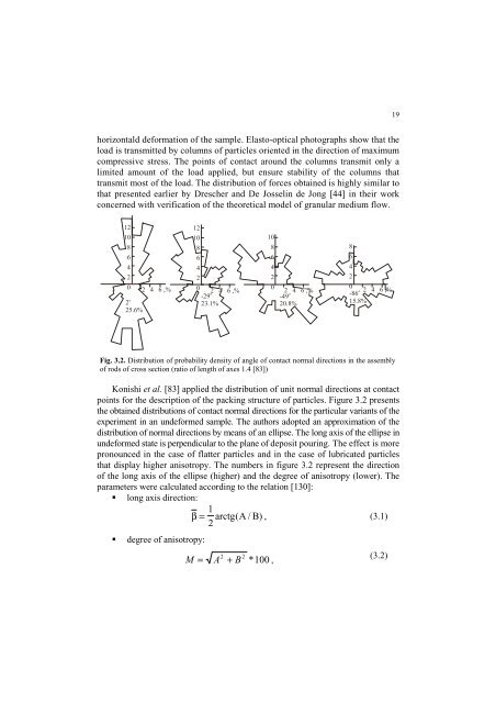
Fig. 3.2. Distribution of probability density of angle of contact normal directions in the assembly<br />
of rods of cross section (ratio of length of axes 1.4 [83])<br />
Konishi et al. [83] applied the distribution of unit normal directions at contact<br />
points for the description of the packing structure of particles. Figure 3.2 presents<br />
the obtained distributions of contact normal directions for the particular variants of the<br />
exper<strong>im</strong>ent in an undeformed sample. The authors adopted an approx<strong>im</strong>ation of the<br />
distribution of normal directions by means of an ellipse. The long axis of the ellipse in<br />
undeformed state is perpendicular to the plane of deposit pouring. The effect is more<br />
pronounced in the case of flatter particles and in the case of lubricated particles<br />
that display higher anisotropy. The numbers in figure 3.2 represent the direction<br />
of the long axis of the ellipse (higher) and the degree of anisotropy (lower). The<br />
parameters were calculated according to the relation [130]:<br />
long axis direction:<br />
1<br />
β = arctg(A / B) , (3.1)<br />
2<br />
<br />
degree of anisotropy:<br />
2 2<br />
M = A + B<br />
* 100 ,<br />
(3.2)