

DEMO - 1965 Ford Truck Shop Manual - ForelPublishing.com
DEMO - 1965 Ford Truck Shop Manual - ForelPublishing.com
DEMO - 1965 Ford Truck Shop Manual - ForelPublishing.com

You also want an ePaper? Increase the reach of your titles
YUMPU automatically turns print PDFs into web optimized ePapers that Google loves.
2-52 GROUP 2-BRAKES<br />
seats squarely on the slave cylinder<br />
body, and tighten the bushing securely.<br />
9. Coat the piston bores in the<br />
slave cylinder body with heavy-duty<br />
brake fluid. Dip the hydraulic cylinder<br />
piston, seals, spring retainer, and<br />
spring in the brake fluid.<br />
10. Install the hydraulic piston in<br />
the slave cylinder bore with the recessed<br />
end (or the large bore of the<br />
piston) toward the push rod bushing.<br />
Carefully position the piston cup<br />
with the recessed end toward the<br />
large spring, spring retainer, and<br />
spring on top of the piston.<br />
On a frame-mounted booster, install<br />
the spring seat in the spring<br />
coils.<br />
11. Position a new copper gasket<br />
on the end plug and screw the plug<br />
in the slave cylinder. Tighten the<br />
end plug securely.<br />
12. Dip the control valve piston<br />
and diaphragm in the heavy-duty<br />
CONTROL TUBE<br />
CONTROL VALVE BODY<br />
AIR INLET TUBE<br />
AND COVER<br />
SNAP RING<br />
SPRING<br />
SEAL<br />
brake fluid. Position the control<br />
valve spring on the diaphragm with<br />
the small end of the spring over the<br />
piston boss.<br />
13. Position the control valve<br />
body over the spring, align the scribe<br />
marks, install the valve body on the<br />
slave cylinder body and secure with<br />
4 attaching bolts and lock washers.<br />
Tighten the bolts securely.<br />
14. Position a new gasket on the<br />
control valve body, position the<br />
valve body cover over the gasket<br />
and secure the cover with 4 bolts<br />
and lock washers. Tighten the bolts<br />
securely.<br />
15. Position the collar over the<br />
threaded end of the push rod. Position<br />
the spring retainer in the spring<br />
as shown in the insert in Fig. 29. Insert<br />
the push rod and collar in the<br />
coils of the spring and through the<br />
retainer. Position the diaphragm<br />
over the threaded end of the push<br />
rod and secure it with the push rod<br />
RUBBER GASKET-<br />
CONTROL VALVE CYLINDER<br />
STOP WASHER<br />
GASKET •<br />
DIAPHRAGM<br />
nut. Tighten the nut securely. After<br />
the nut is tightened coat the threads<br />
of the push rod with shellac to prevent<br />
leakage. Coat the push rod with<br />
heavy-duty type brake fluid.<br />
16. Place the return spring over<br />
the push rod bushing.<br />
17. Place the rear body on top of<br />
the diaphragm with the scriber mark<br />
on the rear body in alignment with<br />
that on the front body. Compress<br />
the return spring, and install and<br />
tighten the clamp, making certain<br />
the diaphragm bead is properly positioned<br />
between the 2 halves of<br />
the body.<br />
18. Install the by-pass tube.<br />
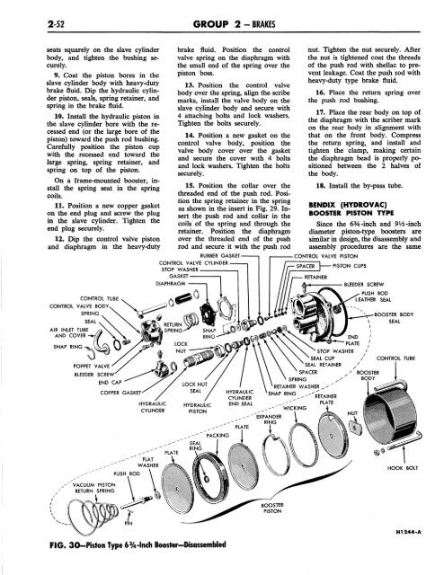
BENDIX (HYDROVAC)<br />
BOOSTER PISTON TYPE<br />
Since the 6%-inch and 9Vi-inch<br />
diameter piston-type boosters are<br />
similar in design, the disassembly and<br />
assembly procedures are the same<br />
CONTROL VALVE PISTON<br />
SPRING<br />
PISTON CUPS<br />
BLEEDER SCREW<br />
END<br />
PLATE<br />
STOP WASHER<br />
SEAL CUP<br />
SEAL RETAINER<br />
SPACER<br />
RETAINER WASHER<br />
SNAP RING<br />
PUSH ROD<br />
LEATHER SEAL<br />
BOOSTER BODY<br />
SEAL<br />
CONTROL TUBE<br />
HOOK BOLT<br />
BOOSTER<br />
PISTON<br />
FIG. 30-Piston Type 6%-lnch Booster-Disassembled<br />
H1244-A


