

DEMO - 1965 Ford Truck Shop Manual - ForelPublishing.com
DEMO - 1965 Ford Truck Shop Manual - ForelPublishing.com
DEMO - 1965 Ford Truck Shop Manual - ForelPublishing.com

You also want an ePaper? Increase the reach of your titles
YUMPU automatically turns print PDFs into web optimized ePapers that Google loves.
PART 2-7-AIR BRAKES 2-83<br />
2. Position the valve assembly to<br />
the mounting bracket and install three<br />
retaining bolts.<br />
3. Assemble the control valve actuating<br />
arm to the mounting bracket<br />
with clevis and cotter key (Fig. 19).<br />
4. Connect the stop light wires (2<br />
nuts and flat washers), and connect<br />
the battery cable.<br />
5. Connect the brake service line(s)<br />
to the upper ports in the valve.<br />
6. Connect the <strong>com</strong>pressor governor<br />
line and the reservoir pressure<br />
line(s) to the lower ports in the valve.<br />
7. Start the engine to build up<br />
pressure and check for leaks.<br />
8. Adjust the valve linkage.<br />
STOP LIGHT SWITCH<br />
If the stop light does not operate,<br />
connect a jumper wire across the two<br />
switch terminals (Fig. 17). If the<br />
light now lights, replace the switch.<br />
If the light still does not light, repair<br />
or replace the two switch lead wires<br />
as necessary.<br />
REMOVAL<br />
1. Disconnect the wires from the<br />
two terminals.<br />
2. Turn the assembly out of the<br />
outlet port of the control valve.<br />
INSTALLATION<br />
1. Screw the new switch into the<br />
port, and connect the wires to the<br />
switch terminals.<br />
QUICK RELEASE VALVE AND<br />
RELAY VALVE<br />
The quick release valve is mounted<br />
as shown in Fig. 1. The relay valve<br />
is used on tandem models and is<br />
mounted as shown in Fig. 20. The<br />
following procedure applies to both<br />
valves with one exception. Before<br />
removing the relay valve, the system<br />
must be exhausted of air pressure.<br />
This is unnecessary when removing<br />
the quick release valve.<br />
REMOVAL<br />
1. Disconnect the air lines at the<br />
valve.<br />
TO REARWARD<br />
REAR BRAKE<br />
A.*'--<br />
FROM FOOT<br />
CONTROL VALVE<br />
RESERVOIR<br />
PRESSURE REAR BRAKE H1047-A<br />
FIG. 20-Relay Valve<br />
2. Remove the mounting bolts<br />
and remove the valve.<br />
INSTALLATION<br />
1. Mount the valve in place and<br />
install and tighten the mounting<br />
bolts and nuts.<br />
2. Inspect the exhaust port to be<br />
sure that it is not plugged.<br />
3. Connect the air lines as shown<br />
in Fig 20.<br />
MAJOR REPAIR OPERATIONS<br />
Major repair operation is applicable<br />
only to the brake chamber. If<br />
any of the <strong>com</strong>ponents listed below<br />
are found to be defective they must<br />
be replaced:<br />
Slack Adjuster<br />
Front Camshaft<br />
Rear Camshaft<br />
Foot Control Valve<br />
Stop Light Switch<br />
Quick Release ValVe<br />
Relay Valve<br />
BRAKE CHAMBER<br />
DISASSEMBLY<br />
1. Before disassembling the brake<br />
chamber, mark both the non-pressure<br />
and pressure plates with relation<br />
to the clamping ring so that the<br />
bolts of the clamping ring can be<br />
placed at the same location during<br />
assembly. This will eliminate the<br />
possibility of installation interference<br />
when the brake chamber is installed<br />
on the truck.<br />
2. Pull the push rod outward<br />
against the spring so as to <strong>com</strong>press<br />
the spring and thus relieve the tension<br />
of the spring on the diaphragm<br />
and clamp ring (Fig. 21). Clamp the<br />
push rod in this position by using a<br />
vise or vise grip pliers on the rod at<br />
the non-pressure plate.<br />
3. Remove the two clamp ring<br />
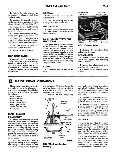
NON-PRESSURE<br />
PLATE<br />
DIAPHRAGM<br />
PUSH ROD<br />
ASSEMBLY<br />
PRESSURE<br />
PLATE<br />
FIG. 21-Brake Chamber<br />
Assembly<br />
CLAMP<br />
RING<br />
H1141-A<br />
nuts and bolts. Spread the clamp<br />
ring slightly, and push the clamp ring<br />
off of the non-pressure plate half of<br />
the chamber and onto the pressure<br />
plate half.<br />
4. Remove the pressure plate and<br />
diaphragm assembly from the nonpressure<br />
plate half of the chamber.<br />
5. Remove the yoke and lock nut<br />
from the push rod. Release the vise<br />
clamp from the push rod. Remove<br />
the push rod assembly, return spring,<br />
seal, and seal spring from the nonpressure<br />
plate half of the chamber.<br />
ASSEMBLY<br />
Always be sure that the correct<br />
return spring is used in any brake<br />
chamber. Also be sure that the brake<br />
chamber on the opposite side of the<br />
axle has the same return spring;<br />
otherwise uneven braking will result.<br />
If a new diaphragm is installed in<br />
the brake chamber on one side of<br />
the axle, a new one should be installed<br />
in the corresponding brake<br />
chamber on the opposite side also;<br />
otherwise uneven braking may result.


