

DEMO - 1965 Ford Truck Shop Manual - ForelPublishing.com
DEMO - 1965 Ford Truck Shop Manual - ForelPublishing.com
DEMO - 1965 Ford Truck Shop Manual - ForelPublishing.com

Create successful ePaper yourself
Turn your PDF publications into a flip-book with our unique Google optimized e-Paper software.
2-78 GROUP 2-BRAKES<br />
STOPMASTER BRAKES<br />
The Stopmaster brakes are available<br />
as optional equipment on H-<br />
Model trucks. The Fail-Safe units<br />
and automatic adjusters are available<br />
as additional optional features<br />
for use with the Stopmaster brake.<br />
The Fail-Safe unit is covered in<br />
Part 2-3.<br />
Two air chamber and actuator<br />
assemblies, one at each end of the<br />
brake shoes, force the shoes against<br />
the drum (Fig. 14). With this design<br />
both shoes do an equal amount of<br />
work resulting in a balanced and<br />
equal braking force in either direction<br />
of truck travel.<br />
System air pressure enters each<br />
pressure housing and moves the diaphragm<br />
and plate against the wedge<br />
(Fig. 23). The diaphragm plate and<br />
push rod assembly pushes the wedge<br />
between the two rollers forcing the<br />
plungers against the brake shoes to<br />
apply the brakes (Fig. 14). As pressure<br />
is released, the wedge springs<br />
pull the wedges out of the rollers<br />
allowing the shoe retracting springs<br />
to pull the shoes away from the drum<br />
and force the plungers back into<br />
their actuator housings.<br />
IN-TRUCK ADJUSTMENTS AND REPAIRS<br />
FOOT CONTROL VALVE<br />
ADJUSTMENT<br />
F-, B-, C-, N- AND<br />
T-SERIES TRUCKS<br />
The foot control valve is bolted to<br />
a mounting plate (Fig. 17) on the<br />
lower dash panel (engine side). The<br />
brake treadle pivots on a pin in a<br />
support that is integral with the same<br />
mounting plate on the passenger side<br />
of the dash panel (Fig. 18). This<br />
CLEVIS ROD<br />
VALVE ACTUATING ARM<br />
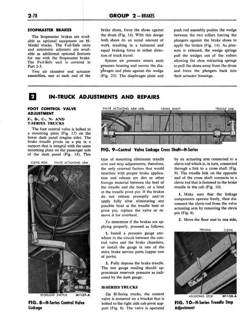
VALVE ACTUATING ARM LINK<br />
CROSS SHAFT<br />
FIG. 9-Control Valve Linkage Cross Shaft-H-Series<br />
type of mounting eliminates treadle<br />
arm and stop adjustments; therefore,<br />
the only external factors that would<br />
interfere with proper brake application<br />
and release are dirt or other<br />
foreign material between the heel of<br />
the treadle and the body, or a bind<br />
at the treadle pivot pin. If the brakes<br />
do not release promptly and/or<br />
apply fully after eliminating any<br />
possible bind at the treadle heel or<br />
pivot pin, replace the valve or remove<br />
it for overhaul.<br />
To determine if the brakes are applying<br />
properly, proceed as follows:<br />
1. Install a pressure gauge anywhere<br />
in the circuit between the control<br />
valve and the brake chambers,<br />
or install the gauge in one of the<br />
extra brake service ports (upper row<br />
of ports).<br />
2. Fully depress the brake treadle.<br />
The test gauge reading should approximate<br />
reservoir pressure as indicated<br />
by the dash gauge.<br />
TREADLE LINK<br />
by an actuating arm connected to a<br />
clevis rod which is, in turn, connected<br />
through a link to a cross shaft (Fig.<br />
9). The treadle link on the opposite<br />
end of the cross shaft connects to a<br />
clevis rod that is fastened to the brake<br />
treadle in the cab (Fig. 10).<br />
1. Make sure that the linkage<br />
<strong>com</strong>ponents operate freely, then disconnect<br />
the clevis rod from the valve<br />
actuating arm by removing the clevis<br />
pin (Fig. 8).<br />
2. Move the floor mat to one side,<br />
TREADLE<br />
CLEVIS<br />
STOPLIGHT SWITCH<br />
FIG. 8-H-Series Control Valve<br />
Linkage<br />
H-SERIES TRUCKS<br />
On H-Series trucks, the control<br />
valve is mounted on a bracket that is<br />
bolted to the right side cab pivot support<br />
(Fig. 8). The valve is operated<br />
ADJUSTING STOP<br />
H1138-A<br />
FIG. 10-H-Series Treadle Stop<br />
Adjustment


