

DEMO - 1965 Ford Truck Shop Manual - ForelPublishing.com
DEMO - 1965 Ford Truck Shop Manual - ForelPublishing.com
DEMO - 1965 Ford Truck Shop Manual - ForelPublishing.com

You also want an ePaper? Increase the reach of your titles
YUMPU automatically turns print PDFs into web optimized ePapers that Google loves.
2-70 GROUP 2-BRAKES<br />
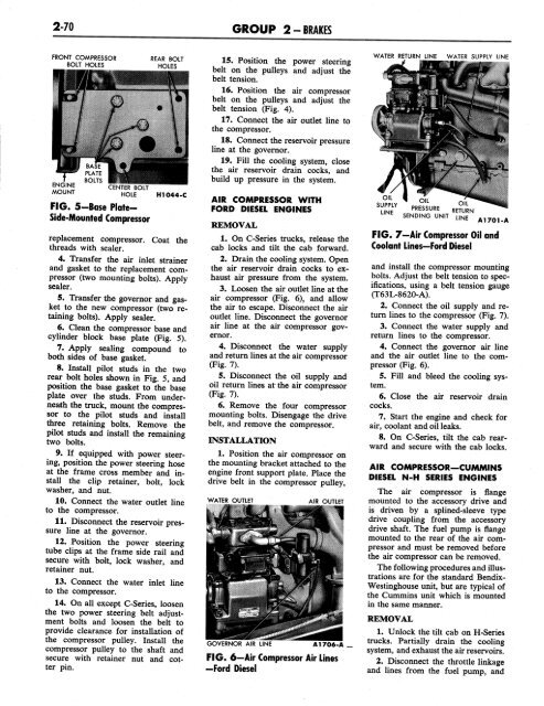
FRONT COMPRESSOR<br />
BOLT HOLES<br />
ENGINE<br />
MOUNT<br />
CENTER BOLT<br />
HOLE<br />
FIG. 5-Base Plate-<br />
Side-Mounted Compressor<br />
REAR BOLT<br />
HOLES<br />
H1044-C<br />
replacement <strong>com</strong>pressor. Coat the<br />
threads with sealer.<br />
4. Transfer the air inlet strainer<br />
and gasket to the replacement <strong>com</strong>pressor<br />
(two mounting bolts). Apply<br />
sealer.<br />
5. Transfer the governor and gasket<br />
to the new <strong>com</strong>pressor (two retaining<br />
bolts). Apply sealer.<br />
6. Clean the <strong>com</strong>pressor base and<br />
cylinder block base plate (Fig. 5).<br />
7. Apply sealing <strong>com</strong>pound to<br />
both sides of base gasket.<br />
8. Install pilot studs in the two<br />
rear bolt holes shown in Fig. 5, and<br />
position the base gasket to the base<br />
plate over the studs. From underneath<br />
the truck, mount the <strong>com</strong>pressor<br />
to the pilot studs and install<br />
three retaining bolts. Remove the<br />
pilot studs and install the remaining<br />
two bolts.<br />
9. If equipped with power steering,<br />
position the power steering hose<br />
at the frame cross member and install<br />
the clip retainer, bolt, lock<br />
washer, and nut.<br />
10. Connect the water outlet line<br />
to the <strong>com</strong>pressor.<br />
11. Disconnect the reservoir pressure<br />
line at the governor.<br />
12. Position the power steering<br />
tube clips at the frame side rail and<br />
secure with bolt, lock washer, and<br />
retainer nut.<br />
13. Connect the water inlet line<br />
to the <strong>com</strong>pressor.<br />
14. On all except C-Series, loosen<br />
the two power steering belt adjustment<br />
bolts and loosen the belt to<br />
provide clearance for installation of<br />
the <strong>com</strong>pressor pulley. Install the<br />
<strong>com</strong>pressor pulley to the shaft and<br />
secure with retainer nut and cotter<br />
pin.<br />
15. Position the power steering<br />
belt on the pulleys and adjust the<br />
belt tension.<br />
16. Position the air <strong>com</strong>pressor<br />
belt on the pulleys and adjust the<br />
belt tension (Fig. 4).<br />
17. Connect the air outlet line to<br />
the <strong>com</strong>pressor.<br />
18. Connect the reservoir pressure<br />
line at the governor.<br />
19. Fill the cooling system, close<br />
the air reservoir drain cocks, and<br />
build up pressure in the system.<br />
AIR COMPRESSOR WITH<br />
FORD DIESEL ENGINES<br />
REMOVAL<br />
1. On C-Series trucks, release the<br />
cab locks and tilt the cab forward.<br />
2. Drain the cooling system. Open<br />
the air reservoir drain cocks to exhaust<br />
air pressure from the system.<br />
3. Loosen the air outlet line at the<br />
air <strong>com</strong>pressor (Fig. 6), and allow<br />
the air to escape. Disconnect the air<br />
outlet line. Disconnect the governor<br />
air line at the air <strong>com</strong>pressor governor.<br />
4. Disconnect the water supply<br />
and return lines at the air <strong>com</strong>pressor<br />
(Fig. 7).<br />
5. Disconnect the oil supply and<br />
oil return lines at the air <strong>com</strong>pressor<br />
(Fig. 7).<br />
6. Remove the four <strong>com</strong>pressor<br />
mounting bolts. Disengage the drive<br />
belt, and remove the <strong>com</strong>pressor.<br />
INSTALLATION<br />
1. Position the air <strong>com</strong>pressor on<br />
the mounting bracket attached to the<br />
engine front support plate. Place the<br />
drive belt in the <strong>com</strong>pressor pulley,<br />
WATER OUTLET<br />
GOVERNOR AIR LINE<br />
AIR OUTLET<br />
A1706-A _<br />
FIG. 6—Air Compressor Air Lines<br />
-<strong>Ford</strong> Diesel<br />
WATER RETURN LINE<br />
WATER SUPPLY LINE<br />
LINE<br />
A1701<br />
FIG. 7—Air Compressor Oil and<br />
Coolant Lines—<strong>Ford</strong> Diesel<br />
J<br />
and install the <strong>com</strong>pressor mounting<br />
bolts. Adjust the belt tension to specifications,<br />
using a belt tension gauge<br />
(T63L-8620-A).<br />
2. Connect the oil supply and return<br />
lines to the <strong>com</strong>pressor (Fig. 7).<br />
3. Connect the water supply and<br />
return lines to the <strong>com</strong>pressor.<br />
4. Connect the governor air line<br />
and the air outlet line to the <strong>com</strong>pressor<br />
(Fig. 6).<br />
5. Fill and bleed the cooling system.<br />
6. Close the air reservoir drain<br />
cocks.<br />
7. Start the engine and check for<br />
air, coolant and oil leaks.<br />
8. On C-Series, tilt the cab rearward<br />
and secure with the cab locks.<br />
AIR COMPRESSOR—CUMMINS<br />
DIESEL N-H SERIES ENGINES<br />
The air <strong>com</strong>pressor is flange<br />
mounted to the accessory drive and<br />
is driven by a splined-sleeve type<br />
drive coupling from the accessory<br />
drive shaft. The fuel pump is flange<br />
mounted to the rear of the air <strong>com</strong>pressor<br />
and must be removed before<br />
the air <strong>com</strong>pressor can be removed.<br />
The following procedures and illustrations<br />
are for the standard Bendix-<br />
Westinghouse unit, but are typical of<br />
the Cummins unit which is mounted<br />
in the same manner.<br />
REMOVAL<br />
1. Unlock the tilt cab on H-Series<br />
trucks. Partially drain the cooling<br />
system, and exhaust the air reservoirs.<br />
2. Disconnect the throttle linkage<br />
and lines from the fuel pump, and


