

DEMO - 1965 Ford Truck Shop Manual - ForelPublishing.com
DEMO - 1965 Ford Truck Shop Manual - ForelPublishing.com
DEMO - 1965 Ford Truck Shop Manual - ForelPublishing.com

Create successful ePaper yourself
Turn your PDF publications into a flip-book with our unique Google optimized e-Paper software.
PART 2-4 - VACUUM BOOSTERS 2-57<br />
LOCK NUT<br />
BLEEDER SCREW<br />
NUT<br />
NUT<br />
PISTON<br />
ROD<br />
RETAINER<br />
HYDRAULIC CYLINDER<br />
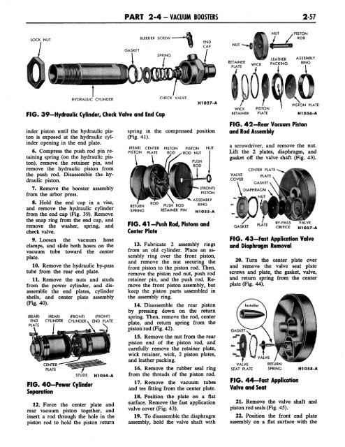
FIG. 39-Hydraulic Cylinder, Check Valve and End Cap<br />
inder piston until the hydraulic piston<br />
is exposed at the hydraulic cylinder<br />
opening in the end plate.<br />
6. Compress the push rod pin retaining<br />
spring (on the hydraulic piston),<br />
remove the retainer pin, and<br />
remove the hydraulic piston from<br />
the push rod. Disassemble the hydraulic<br />
piston.<br />
7. Remove the booster assembly<br />
from the arbor press.<br />
8. Hold the end cap in a vise,<br />
and remove the hydraulic cylinder<br />
from the end cap (Fig. 39). Remove<br />
the snap ring from the end cap, and<br />
remove the washer, spring, and<br />
check valve.<br />
9. Loosen the vacuum hose<br />
clamps, and slide both hoses on the<br />
vacuum tube toward the center<br />
plate.<br />
10. Remove the hydraulic by-pass<br />
tube from the rear end plate.<br />
11. Remove the nuts and studs<br />
from the power cylinder, and disassemble<br />
the end plates, cylinder<br />
shells, and center plate assembly<br />
(Fig. 40).<br />
(REAR)<br />
END<br />
PLATE<br />
(REAR)<br />
CYLINDER<br />
CENTER<br />
PLATE<br />
(FRONT)<br />
CYLINDER<br />
STUDS<br />
FIG. 40—Power Cylinder<br />
Separation<br />
H1054-A<br />
12. Force the center plate and<br />
rear vacuum piston together, and<br />
insert a rod through the hole in the<br />
piston rod to hold the piston return<br />
CHECK VALVE<br />
H1027-A<br />
spring in the <strong>com</strong>pressed position<br />
(Fig. 41).<br />
(REAR) CENTER PISTON PISTON NUT<br />
PISTON PLATE ROD ^ ROD NUT<br />
^<br />
PUSH ROD<br />
RETAINER PIN<br />
PUSH<br />
ROD<br />
(FRONT)<br />
PISTON<br />
ASSEMBLY<br />
RING<br />
H1055-A<br />
FIG. 41 -Push Rod, Pistons and<br />
Center Plate<br />
13. Fabricate 2 assembly rings<br />
from an old cylinder. Place an assembly<br />
ring over the front piston,<br />
and remove the nut securing the<br />
front piston to the piston rod. Then,<br />
remove the piston rod nut, push rod<br />
retainer pin, and the push rod. Remove<br />
the front piston assembly, but<br />
keep the piston parts assembled in<br />
the assembly ring.<br />
14. Disassemble the rear piston<br />
by pressing down on the return<br />
spring. Then, remove the rod, center<br />
plate, and return spring from the<br />
piston rod (Fig. 42).<br />
15. Remove the nut from the rear<br />
piston end of the piston rod, and<br />
carefully remove the retainer plate,<br />
wick retainer, wick, 2 piston plates,<br />
and leather packing.<br />
16. Remove the rubber seal ring<br />
from the threads of the piston rod.<br />
17. Remove the vacuum tubes<br />
and tee fitting from the center plate.<br />
18. Position the plate on a flat<br />
surface. Remove the fast application<br />
valve cover (Fig. 43).<br />
19. To disassemble the diaphragm<br />
assembly, hold the valve shaft with<br />
WICK<br />
RETAINER<br />
PISTON<br />
PLATE<br />
PISTON PLATE<br />
FIG. 42-Rear Vacuum Piston<br />
and Rod Assembly<br />
H1056-A<br />
a screwdriver, and remove the nut.<br />
Lift the 2 plates, diaphragm, and<br />
gasket off the valve shaft (Fig. 43).<br />
VALVE<br />
COVER<br />
GASKET<br />
CENTER PLATE<br />
PLATE<br />
GASKET<br />
DIAPHRAGM<br />
NUT<br />
PLATE<br />
VALVE<br />
H1057-A<br />
FIG. 43-Fast Application Valve<br />
and Diaphragm Removal<br />
20. Turn the center plate over<br />
and remove the valve seat plate<br />
screws and plate, the gasket, valve,<br />
and return spring from the center<br />
plate (Fig. 44).<br />
FIG. 44-Fast Application<br />
Valve and Seat<br />
H1058-A<br />
21. Remove the valve shaft and<br />
piston rod seals (Fig. 45).<br />
22. Position the front end plate<br />
assembly on a flat surface with the


