

DEMO - 1965 Ford Truck Shop Manual - ForelPublishing.com
DEMO - 1965 Ford Truck Shop Manual - ForelPublishing.com
DEMO - 1965 Ford Truck Shop Manual - ForelPublishing.com

You also want an ePaper? Increase the reach of your titles
YUMPU automatically turns print PDFs into web optimized ePapers that Google loves.
2-68 GROUP 2-BRAKES<br />
Connections in this system are to<br />
the reservoir and <strong>com</strong>pressor unloading<br />
ports. There also is an exhaust<br />
port.<br />
Reservoir air pressure enters the<br />
D-2 governor at one of its reservoir<br />
ports and acts on the area of the<br />
piston and beneath the inlet and exhaust<br />
valve. As the air pressure<br />
builds up, the piston moves against<br />
the resistance of the pressure setting<br />
spring. The piston and inlet and exhaust<br />
valve move up when the reservoir<br />
air pressure reaches the cutout<br />
setting of the governor.<br />
The exhaust stem seats on the inlet<br />
and exhaust valve and then the<br />
inlet passage opens. Reservoir air<br />
pressure then flows by the open<br />
inlet valve, through the passage in<br />
the piston, and out the unloader port<br />
to the <strong>com</strong>pressor unloading mechanism.<br />
The air, besides flowing to<br />
the <strong>com</strong>pressor unloading mechanism,<br />
also flows around the piston<br />
and acts on the additional area of the<br />
piston. This additive force, which results<br />
from a larger area on the piston,<br />
assures a positive action and<br />
fully opens the inlet valve.<br />
As the system reservoir air pressure<br />
drops to the cut-in setting of the<br />
governor, the force exerted by the air<br />
pressure on the piston will be reduced<br />
so that the pressure setting<br />
spring will move the piston down.<br />
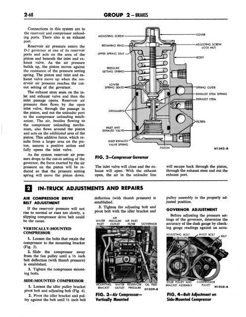
ADJUSTING SCREW<br />
RETAINING RING<br />
UPPER SPRING SEAT<br />
PRESSURE<br />
SETTING SPRING<br />
LOWER<br />
SPRING SEATS<br />
GROMMETS<br />
INLET AND<br />
EXHAUST VALVE<br />
INLET-EXHAUST<br />
VALVE SPRING<br />
FIG. 2—Compressor Governor<br />
The inlet valve will close and the exhaust<br />
will open. With the exhaust<br />
open, the air in the unloader line<br />
PISTON<br />
COVER<br />
ADJUSTING SCREW<br />
LOCK NUT<br />
BODY<br />
ING GUIDE<br />
EXHAUST STEM SPRING<br />
EXHAUST STEM<br />
FILTERS<br />
H1342-A<br />
will escape back through the piston,<br />
through the exhaust stem and out the<br />
exhaust port.<br />
IN-TRUCK ADJUSTMENTS AND REPAIRS<br />
AIR COMPRESSOR DRIVE<br />
BELT ADJUSTMENT<br />
If the reservoir pressure will not<br />
rise to normal or rises too slowly, a<br />
slipping <strong>com</strong>pressor drive belt could<br />
be the cause.<br />
VERTICALLY-MOUNTED<br />
COMPRESSOR<br />
1. Loosen the bolts that retain the<br />
<strong>com</strong>pressor to the mounting bracket<br />
(Fig. 3).<br />
2. Slide the <strong>com</strong>pressor away<br />
from the fan pulley until a Vi inch<br />
belt deflection (with thumb pressure)<br />
is established.<br />
3. Tighten the <strong>com</strong>pressor mounting<br />
bolts.<br />
SIDE-MOUNTED COMPRESSOR<br />
1. Loosen the idler pulley bracket<br />
pivot bolt and adjusting bolt (Fig. 4).<br />
2. Pivot the idler bracket and pulley<br />
against the belt until Vi inch belt<br />
deflection (with thumb pressure) is<br />
established.<br />
3. Tighten the adjusting bolt and<br />
pivot bolt with the idler bracket and<br />
AIR<br />
WATER PRESSURE AIR INLET<br />
INLET OUTLET FILTER GOVERNOR<br />
FIG. 3—Air Compressor—<br />
Vertically Mounted<br />
OIL FEED<br />
H1039-B<br />
pulley assembly in the properly adjusted<br />
position.<br />
GOVERNOR ADJUSTMENT<br />
Before adjusting the pressure settings<br />
of the governor, determine the<br />
accuracy of the dash gauge by checking<br />
gauge readings against an accu-<br />
ADJUSTING BOLT<br />
)LER PULLEY AND<br />
BRACKET ASSEMBLY<br />
PIVOT BOLT<br />
BELT<br />
COMPRESSOR<br />
PULLEY<br />
H1038-A<br />
FIG. 4-Belt Adjustment on<br />
Side-Mounted Compressor


