

NV52/NV54/NV56/NV58 Service Guide - tim.id.au
NV52/NV54/NV56/NV58 Service Guide - tim.id.au
NV52/NV54/NV56/NV58 Service Guide - tim.id.au

You also want an ePaper? Increase the reach of your titles
YUMPU automatically turns print PDFs into web optimized ePapers that Google loves.
www.gateway.com<br />
Replacing the modem board<br />
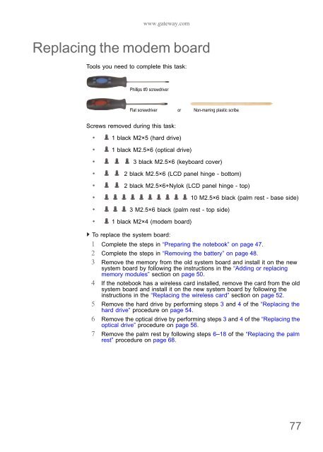
Tools you need to complete this task:<br />
Phillips #0 screwdriver<br />
Flat screwdriver or Non-marring plastic scribe<br />
Screws removed during this task:<br />
• 1 black M2×5 (hard drive)<br />
• 1 black M2.5×6 (optical drive)<br />
• 3 black M2.5×6 (keyboard cover)<br />
• 2 black M2.5×6 (LCD panel hinge - bottom)<br />
• 2 black M2.5×6+Nylok (LCD panel hinge - top)<br />
• 10 M2.5×6 black (palm rest - base s<strong>id</strong>e)<br />
• 3 M2.5×6 black (palm rest - top s<strong>id</strong>e)<br />
• 1 black M2×4 (modem board)<br />
To replace the system board:<br />
1 Complete the steps in “Preparing the notebook” on page 47.<br />
2 Complete the steps in “Removing the battery” on page 48.<br />
3 Remove the memory from the old system board and install it on the new<br />
system board by following the instructions in the “Adding or replacing<br />
memory modules” section on page 50.<br />
4 If the notebook has a wireless card installed, remove the card from the old<br />
system board and install it on the new system board by following the<br />
instructions in the “Replacing the wireless card” section on page 52.<br />
5 Remove the hard drive by performing steps 3 and 4 of the “Replacing the<br />
hard drive” procedure on page 54.<br />
6 Remove the optical drive by performing steps 3 and 4 of the “Replacing the<br />
optical drive” procedure on page 56.<br />
7 Remove the palm rest by following steps 6–18 of the “Replacing the palm<br />
rest” procedure on page 68.<br />
77


