TSUBAKI EMERSON CAM CLUTCH
TSUBAKI EMERSON CAM CLUTCH
TSUBAKI EMERSON CAM CLUTCH

Create successful ePaper yourself
Turn your PDF publications into a flip-book with our unique Google optimized e-Paper software.
www.bergab.ru Берг АБ bergab@ya.ru Тел. (495)-228-06-21, факс (495) 223-3071<br />
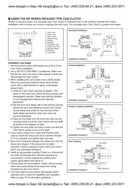
■ USING THE BR SERIES PACKAGE TYPE <strong>CAM</strong> <strong>CLUTCH</strong><br />
Similar to previous types, the package type Cam Clutch is designed into a ball bearing cassette that makes<br />
installation with a torque arm and/or coupling fast and easy. The package type Cam Clutch is grease lubricated.<br />
q Inner race<br />
w Outer race<br />
e Cam cage<br />
r Stopper ring<br />
t Flange<br />
y Bearing<br />
u Labyrinth seal<br />
i Hollow hex bolt<br />
o Spring washer<br />
!0 Packing<br />
!1 Lube port<br />
Horizontal Installation<br />
Installation example 1:<br />
Installation and Usage<br />
1. We recommend using shaft tolerances of h6 or h7 for<br />
Cam Clutch installation.<br />
2. Use a ISO R773 (DIN 6885.1) parallel key. Make sure<br />
that the key does not move in the keyway. A loose key<br />
will damage the Cam Clutch.<br />
3. When installing the Cam Clutch over a shaft, please<br />
follow the procedure outlined below. Never hit the<br />
clutch with a steel hammer or apply unnecessary<br />
impact loads.<br />
1) Verify the Cam Clutch direction of rotation. The<br />
arrow on the inner race shows the free running (cam<br />
disengaged) direction. Make sure that the direction<br />
of cam engagement matches the intended<br />
application.<br />
2) Tap the inner race lightly with a soft hammer moving<br />
around the race circumference so the Cam Clutch<br />
moves slowly and uniformly onto the end of the<br />
shaft. Make sure that the outer race does not<br />
become dislodged.<br />
3) Place an end plate over the inner race and use the<br />
mounting bolts to pull the Cam Clutch onto the shaft<br />
as shown in the diagram at right.<br />
4) Tighten the end plate securely to make sure that the<br />
Cam Clutch cannot move on the shaft.<br />
4. If you using a torque arm, make sure that the bolts<br />
used to mount the torque arm have a tensile strength<br />
of 10.9 or greater, and tighten them securely.<br />
5. Set a 2mm clearance between the torque arm and the<br />
torque arm stopper. If the torque arm is rigidly<br />
mounted, it will be applying a load to the Cam Clutch<br />
which can eventually damage it.<br />
6. Install an appropriate coupling if there is a chance that<br />
the shaft will elongate from thermal expansion as<br />
encountered in some exhaust fan auxiliary drive<br />
system applications (see figure 4).<br />
7. If thrust loads are encountered, install a thrust bearing<br />
which will prevent those thrust loads from being<br />
transferred to the Cam Clutch.<br />
8. The Cam Clutch is pre-packed with grease before<br />
shipment and is ready for installation and operation.<br />
Refer to page 76 for lubrication guidelines.<br />
Vertical Installation<br />
Installation example 2:<br />
Flexible Coupling Installation<br />
Installation example 3:<br />
Gear Coupling<br />
Installation example 4:<br />
www.bergab.ru Берг АБ bergab@ya.ru Тел. 55 (495)-228-06-21, факс (495) 223-3071