TM 3-4240-334-20&P
TM 3-4240-334-20&P
TM 3-4240-334-20&P

You also want an ePaper? Increase the reach of your titles
YUMPU automatically turns print PDFs into web optimized ePapers that Google loves.
<strong>TM</strong> 3-<strong>4240</strong>-<strong>334</strong>-20&P<br />
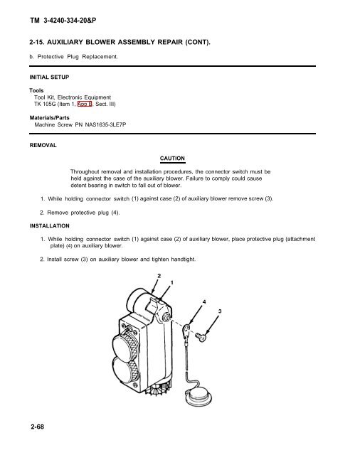
2-15. AUXILIARY BLOWER ASSEMBLY REPAIR (CONT).<br />
b. Protective Plug Replacement.<br />
INITIAL SETUP<br />
Tools<br />
Tool Kit, Electronic Equipment<br />
TK 105G (Item 1, App B, Sect. III)<br />
Materials/Parts<br />
Machine Screw PN NAS1635-3LE7P<br />
REMOVAL<br />
CAUTION<br />
Throughout removal and installation procedures, the connector switch must be<br />
held against the case of the auxiliary blower. Failure to comply could cause<br />
detent bearing in switch to fall out of blower.<br />
1. While holding connector switch (1) against case (2) of auxiliary blower remove screw (3).<br />
2. Remove protective plug (4).<br />
INSTALLATION<br />
1. While holding connector switch<br />
plate) (4) on auxiliary blower.<br />
2. Install screw (3) on auxiliary blower and tighten handtight.<br />
(1) against case (2) of auxiliary blower, place protective plug (attachment<br />
2-68