F-1⢠Installation Manual - Viking Access
F-1⢠Installation Manual - Viking Access
F-1⢠Installation Manual - Viking Access

Create successful ePaper yourself
Turn your PDF publications into a flip-book with our unique Google optimized e-Paper software.
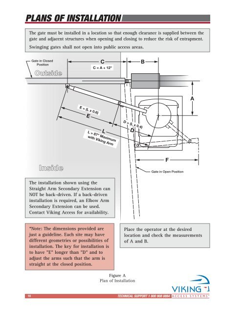
PLANS OF INSTALLATION<br />
The gate must be installed in a location so that enough clearance is supplied between the<br />
gate and adjacent structures when opening and closing to reduce the risk of entrapment.<br />
Swinging gates shall not open into public access areas.<br />
Gate in Closed<br />
Position<br />
Outside<br />
C<br />
C = A + 12"<br />
B<br />
A<br />
E = (L x 0.6)<br />
E<br />
L = 87" Maximum<br />
with <strong>Viking</strong> Arm<br />
L<br />
D = (L x 0.4)<br />
D<br />
Inside<br />
F<br />
Gate in Open Position<br />
The installation shown using the<br />
Straight Arm Secondary Extension can<br />
NOT be back-driven. If a back-driven<br />
installation is required, an Elbow Arm<br />
Secondary Extension can be used.<br />
Contact <strong>Viking</strong> <strong>Access</strong> for availability.<br />
*Note: The dimensions provided are<br />
just a guideline. Each site may have<br />
different geometries or possibilities of<br />
installation. The key for installation is<br />
to have "E" longer than "D" and to<br />
adjust the arms such that the arm is<br />
straight at the closed position.<br />
Place the operator at the desired<br />
location and check the measurements<br />
of A and B.<br />
Figure A<br />
Plan of <strong>Installation</strong><br />
10<br />
TECHNICAL SUPPORT 1 800 908 0884