F-1⢠Installation Manual - Viking Access
F-1⢠Installation Manual - Viking Access
F-1⢠Installation Manual - Viking Access

You also want an ePaper? Increase the reach of your titles
YUMPU automatically turns print PDFs into web optimized ePapers that Google loves.
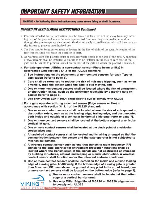
IMPORTANT SAFETY INFORMATION<br />
WARNING - Not following these instructions may cause severe injury or death to persons.<br />
IMPORTANT INSTALLATION INSTRUCTIONS Continued<br />
6. Controls intended for user activation must be located at least six feet (6’) away from any moving<br />
part of the gate and where the user is prevented from reaching over, under, around or<br />
through the gate to operate the controls. Outdoor or easily accessible controls shall have a security<br />
feature to prevent unauthorized use.<br />
7. The Stop and/or Reset button must be located in the line-of-sight of the gate. Activation of the<br />
reset control shall not cause the operator to start.<br />
8. All warning signs and placards must be installed where visible in the area of the gate. A minimum<br />
of two placards shall be installed. A placard is to be installed in the area of each side of the<br />
gate and be visible to persons located on the side of the gate on which the placard is installed.<br />
9. For gate operators utilizing a non-contact sensor (Photo beam or like) in<br />
accordance with section 31.1.1 of the UL325 standard:<br />
a) See instructions on the placement of non-contact sensors for each Type of<br />
application (refer to page 6),<br />
b) Care shall be exercised to reduce the risk of nuisance tripping, such as when<br />
a vehicle, trips the sensor while the gate is still moving, and<br />
c) One or more non-contact sensors shall be located where the risk of entrapment<br />
or obstruction exists, such as the perimeter reachable by a moving gate or<br />
barrier (refer to page 6).<br />
d) Use only Omron E3K-R10K4 photoelectric eye to comply with UL325<br />
10. For a gate operator utilizing a contact sensor (Edge sensor or like) in<br />
accordance with section 31.1.1 of the UL325 standard:<br />
a) One or more contact sensors shall be located where the risk of entrapment or<br />
obstruction exists, such as at the leading edge, trailing edge, and post mounted<br />
both inside and outside of a vehicular horizontal slide gate (refer to page 7).<br />
b) One or more contact sensors shall be located at the bottom edge of a vehicular<br />
vertical lift gate.<br />
c) One or more contact sensors shall be located at the pinch point of a vehicular<br />
vertical pivot gate.<br />
d) A hardwired contact sensor shall be located and its wiring arranged so that the<br />
communication between the sensor and the gate operator is not subjected to<br />
mechanical damage.<br />
e) A wireless contact sensor such as one that transmits radio frequency (RF)<br />
signals to the gate operator for entrapment protection functions shall be<br />
located where the transmission of the signals are not obstructed or impeded<br />
by building structures, natural landscaping or similar obstruction. A wireless<br />
contact sensor shall function under the intended end-use conditions.<br />
f) One or more contact sensors shall be located on the inside and outside leading<br />
edge of a swing gate. Additionally, if the bottom edge of a swing gate is greater<br />
than 6 inches (152 mm) above the ground at any point in its arc of travel, one<br />
or more contact sensors shall be located on the bottom edge (refer to page 7).<br />
g) One or more contact sensors shall be located at the bottom<br />
edge of a vertical barrier (arm).<br />
h) Use only Miller Edge Model MGR20 or MGS20 edge sensor<br />
to comply with UL325<br />
TECHNICAL SUPPORT 1 800 908 0884 3