F-1⢠Installation Manual - Viking Access
F-1⢠Installation Manual - Viking Access
F-1⢠Installation Manual - Viking Access

Create successful ePaper yourself
Turn your PDF publications into a flip-book with our unique Google optimized e-Paper software.
GATE OPERATOR INSTALLATION<br />
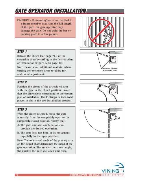
CAUTION - If mounting bar is not welded to<br />
a frame member that runs the full length<br />
of the gate, the gate operator may<br />
damage the gate. Do not weld the bar or<br />
backing plate to a few pickets.<br />
STEP 1<br />
Release the clutch (see page 7). Cut the<br />
extension arms according to the desired plan<br />
of installation (Figure A on page 10).<br />
Note: Leave some additional material when<br />
cutting the extension arms to allow for<br />
additional adjustment.<br />
Remove Excess<br />
Extension Tube<br />
STEP 2<br />
Position the pieces of the articulated arm<br />
with the gate in the closed position. Ensure<br />
that the dimensions correspond to the chosen<br />
plan of installation. Use C-clamps or tack-weld<br />
pieces to aid in the pre-installation process.<br />
STEP 3<br />
With the clutch released, move the gate<br />
manually from the completely open to the<br />
completely closed position. Verify that:<br />
A. The gate and arm combination can<br />
provide the desired operation.<br />
B. The arm does not bind in its movement,<br />
especially in the open position.<br />
Note: The total travel angle of the primary arm<br />
on the output shaft determines the speed of the<br />
gate operation. The smaller the travel angle,<br />
the quicker the gate will open and close.<br />
12 TECHNICAL SUPPORT 1 800 908 0884<br />
16