F-1⢠Installation Manual - Viking Access
F-1⢠Installation Manual - Viking Access
F-1⢠Installation Manual - Viking Access

You also want an ePaper? Increase the reach of your titles
YUMPU automatically turns print PDFs into web optimized ePapers that Google loves.
Delay<br />
3<br />
rlap Delay<br />
1.5<br />
0<br />
Open<br />
Open<br />
OPTIONAL VIKING BLUE Fail INSTALLATION<br />
24V BAT 24VAC<br />
OPEN RIGHT<br />
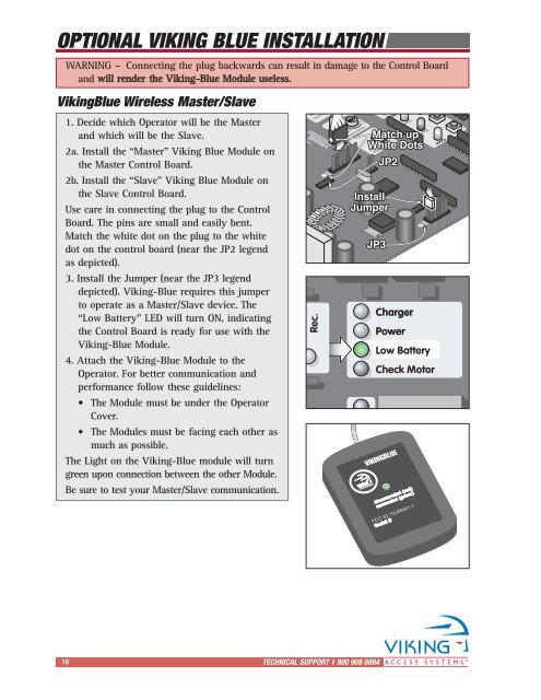
1. Decide which Operator will be the Master<br />
and which will be the Slave.<br />
2a. Install the “Master” <strong>Viking</strong> Blue Module on<br />
Fail<br />
Safe/Secure<br />
the Master Control Board.<br />
2b. Install the “Slave” <strong>Viking</strong> Blue Module on<br />
the Slave Control Board.<br />
Use care in connecting the plug to the Control<br />
Board. The pins are small and easily bent.<br />
Match the white dot on the plug to the white<br />
dot on the control board (near the JP2 legend<br />
as depicted).<br />
3. Install the Jumper (near the JP3 legend<br />
depicted). <strong>Viking</strong>-Blue requires this jumper<br />
Obstruction to operate as a Master/Slave device. The<br />
“Low Sensor Battery” LED will turn ON, indicating<br />
the Control Board is ready for use with the<br />
<strong>Viking</strong>-Blue Module.<br />
4. Attach the <strong>Viking</strong>-Blue Module to the<br />
min. MAX<br />
Operator. For better communication and<br />
performance follow these guidelines:<br />
• The Module must be under the Operator<br />
Cover.<br />
Hold Open<br />
• The Timer Modules must be facing each other as<br />
much as possible.<br />
The Light on the <strong>Viking</strong>-Blue module will turn<br />
green upon connection between the other Module.<br />
Be sure to test your Master/Slave communication.<br />
OPEN LEFT<br />
Charger<br />
Check Motor<br />
Low Low Battery Battery<br />
Power Power<br />
Mag.<br />
Lock<br />
N.C.<br />
COM<br />
N.O.<br />
MAG. LOCK<br />
+28v<br />
Gnd<br />
Radio Station<br />
Safe/Secure<br />
WARNING – Connecting the plug backwards can result in damage to the Control Board<br />
and will render the <strong>Viking</strong>-Blue Module useless.<br />
<strong>Viking</strong>Blue Wireless Master/Slave<br />
Obstruction<br />
Sensor<br />
Hold Open<br />
Timer<br />
60<br />
30<br />
Center<br />
Loop<br />
Reopen<br />
Loop<br />
Rec.<br />
Off 1 Radio<br />
UL<br />
Sens<br />
Reopen<br />
Loop<br />
Center<br />
Loop<br />
+28v<br />
OPEN LEFT<br />
Off 1 UL<br />
Sens<br />
Radio<br />
Rec.<br />
JP2<br />
Radio<br />
Gnd<br />
Sensor<br />
min. MAX<br />
Obstruction<br />
+28v<br />
Gnd<br />
Loop Connector<br />
1.5<br />
UL<br />
Overlap<br />
Delay<br />
Gnd<br />
0<br />
Reopen<br />
30<br />
Hold Open<br />
Timer<br />
Gnd<br />
3<br />
Center<br />
VIKINGBLUE<br />
Gnd<br />
60<br />
Open<br />
Match up<br />
White Dots<br />
Install<br />
Jumper<br />
Mag.<br />
Lock<br />
MAG. Mag. LOCK Lock<br />
JP3<br />
JP2<br />
24V BAT 24V<br />
Charger<br />
Power<br />
disconnected (red)<br />
connected (green)<br />
FCC ID: T9JRN41-1<br />
Serial #<br />
Exit<br />
Gnd<br />
Open Open Commands Commands<br />
Stop<br />
JP3<br />
Low Battery<br />
Strike<br />
Gnd<br />
Close<br />
C35 C36<br />
Check Motor<br />
N.C.<br />
COM<br />
N.O.<br />
Fire<br />
Gnd<br />
OPEN RIGHT<br />
Open<br />
Stop<br />
Guard Guard Station Station<br />
Close<br />
GND<br />
Brake<br />
Open<br />
Stop<br />
Master/Slave<br />
Master/Slave<br />
Close<br />
GND<br />
en<br />
Gnd<br />
Open Commands<br />
Fire<br />
Gnd<br />
Strike<br />
Gnd<br />
Exit<br />
Gnd<br />
Safety Loop Connector<br />
Center<br />
Gnd<br />
Reopen<br />
Gnd<br />
UL<br />
Gnd<br />
+28v<br />
Radio Station<br />
Gnd<br />
Radio<br />
+28v<br />
Gnd<br />
+28v<br />
18<br />
TECHNICAL SUPPORT 1 800 908 0884