F-1⢠Installation Manual - Viking Access
F-1⢠Installation Manual - Viking Access
F-1⢠Installation Manual - Viking Access

Create successful ePaper yourself
Turn your PDF publications into a flip-book with our unique Google optimized e-Paper software.
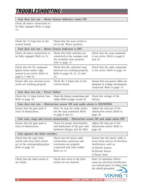
TROUBLESHOOTING<br />
Gate does not run – Motor Sensor indicator comes ON<br />
Check all motor connections to<br />
be fully engaged. Refer to page<br />
15.<br />
Check the 15 Amp fuse in the<br />
control board.<br />
Check that the reset switch is<br />
set in the “Reset’ position.<br />
Gate does not run – Motor Sensor indicator is OFF<br />
Check all motor connections to<br />
be fully engaged. Refer to 15.<br />
Check that the UL command<br />
(photo beam and/or edge<br />
sensor) is not active. Refer to<br />
page 6, 7 and 23.<br />
Ensure that you external accessories<br />
are working properly.<br />
Gate does not run – Power failure<br />
Check the 15 Amp battery fuse.<br />
Refer to page 18.<br />
Check that limit switches are<br />
connected to the common and<br />
the normally close position<br />
refer to page 17.<br />
Check the battery connections and<br />
cables. Refer to page 14 and 18.<br />
Check that the stop command<br />
is not active. Refer to page 8<br />
and 25.<br />
Check the voltage of the<br />
battery.<br />
Gate does not run – Obstruction sensor ON and audio alarm is SOUNDING<br />
Ensure that the gate path is<br />
clear of obstructions.<br />
Note: To stop the audio alarm,<br />
use the stop command. Refer<br />
to page 8 and 27.<br />
Adjust the trim pot of the<br />
obstruction sensor. Refer to<br />
page 28.<br />
Gate runs, stops and reverse momentarily – Obstruction sensor ON and audio alarm OFF<br />
Ensure that the gate path is<br />
clear of obstructions.<br />
Gate ignores the limit switches<br />
Check that the open limit<br />
switch and close limit switch<br />
are in the corresponding place.<br />
Refer to page 16.<br />
Check that the limit switch is<br />
not faulty.<br />
Check that the vehicular loop<br />
detectors are working properly.<br />
Refer to page 20, 21, 22 and<br />
23.<br />
Check the 4 Amps fuse in the<br />
control board.<br />
Check for proper functionality<br />
and lubrication of the gate and<br />
hardware (hinges and the like).<br />
Check that all motor cable<br />
connections, junctions and<br />
extensions are properly<br />
connected and color-coded.<br />
Refer to 15.<br />
Check that wires to the limit<br />
switch are not shorted.<br />
Check that the radio command<br />
is not active. Refer to page 24.<br />
Ensure that you power cables are<br />
adequate in voltage and properly<br />
connected. Refer to page 15.<br />
Adjust the trim pot of the<br />
obstruction sensor. Refer to<br />
page 28.<br />
Ensure that the motor cable is<br />
away from sources of electrical<br />
interference, such as<br />
a) Electric motors<br />
b) Electric fences<br />
c) Power lines.<br />
Note: To minimize effects<br />
cause by electrical interference<br />
use twisted pairs of cables with<br />
the shield grounded.<br />
36 TECHNICAL SUPPORT 1 800 908 0884<br />
29