F-1⢠Installation Manual - Viking Access
F-1⢠Installation Manual - Viking Access
F-1⢠Installation Manual - Viking Access

You also want an ePaper? Increase the reach of your titles
YUMPU automatically turns print PDFs into web optimized ePapers that Google loves.
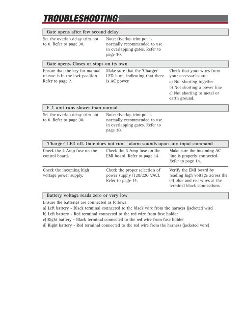
TROUBLESHOOTING<br />
Gate opens after few second delay<br />
Set the overlap delay trim pot<br />
to 0. Refer to page 30.<br />
Note: Overlap trim pot is<br />
normally recommended to use<br />
in overlapping gates. Refer to<br />
page 30.<br />
Gate opens. Closes or stops on its own<br />
Ensure that the key for manual<br />
release is in the lock position.<br />
Refer to page 7.<br />
Make sure that the ‘Charger’<br />
LED is on, indicating that there<br />
is AC power.<br />
Check that your wires from<br />
your accessories are:<br />
a) Not shorting together<br />
b) Not shorting a power line<br />
c) Not shorting to metal or<br />
earth ground.<br />
F-1 unit runs slower than normal<br />
Set the overlap delay trim pot<br />
to 0. Refer to page 30.<br />
Note: Overlap trim pot is<br />
normally recommended to use<br />
in overlapping gates. Refer to<br />
page 30.<br />
‘Charger’ LED off. Gate does not run - alarm sounds upon any input command<br />
Check the 4 Amp fuse on the<br />
control board.<br />
Check the 3 Amp fuse on the<br />
EMI board. Refer to page 14.<br />
Make sure the incoming AC<br />
line is properly connected.<br />
Refer to page 14.<br />
Check the incoming high<br />
voltage power supply.<br />
Check the proper selection of<br />
power supply (120/220 VAC).<br />
Refer to page 14.<br />
Verify the EMI board by<br />
reading high voltage across the<br />
(4) blue and red wires at the<br />
terminal block connections.<br />
Battery voltage reads zero or very low<br />
Ensure the batteries are connected as follows:<br />
a) Left battery - Black terminal connected to the black wire from the harness (jacketed wire)<br />
b) Left battery - Red terminal connected to the red wire from fuse holder<br />
c) Right battery - Black terminal connected to the red wire from fuse holder<br />
d) Right battery - Red terminal connected to the red wire from the harness (jacketed wire)