F-1⢠Installation Manual - Viking Access
F-1⢠Installation Manual - Viking Access
F-1⢠Installation Manual - Viking Access

Create successful ePaper yourself
Turn your PDF publications into a flip-book with our unique Google optimized e-Paper software.
VEHICULAR LOOP DETECTOR INSTALLATION<br />
WARNING –Consult the installation instructions from the loop detector manufacturer. The following<br />
statements are provided as a guide but different requirements may be required by the<br />
vehicular loop detector manufacturer.<br />
Guidelines for Vehicular Loop Detector <strong>Installation</strong><br />
1. Prevent sharp corners in the geometry of the loop sensor.<br />
2. Install the appropriate number of turns for your loop geometry based on the loop perimeter. Use<br />
Table C (below) as a guide.<br />
3. Use XLP (cross-linked-polyethylene) type of wire. This wire reduces the effects of moisture and<br />
other environmental events in altering the functionality of the vehicular loop detector.<br />
4. Twist the lead wire at least 6 turns per foot.<br />
5. Use BACKER-ROD to minimize damage to the loop detector wire prior to using the sealant.<br />
6. Place the loop detector wire and adjust the sensitivity of the vehicular loop detector unit in a<br />
way to minimize the effects of the gate over the loop detector wire.<br />
IMPORTANT – Some of the following parameters may affect the proper functionality of the<br />
vehicular loop detector (consult the installation manual and the manufacturer of the<br />
vehicular loop detector).<br />
• Gate size,<br />
• Number of turns in the loop sensor wire;<br />
• Distance from the loop sensor wire to the gate either at the open or close position.<br />
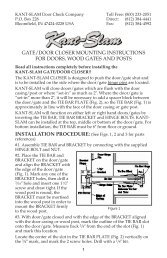
Saw Cut<br />
1" Min.<br />
Sealant<br />
Backer-Rod<br />
Vehicular Loop<br />
Detector Wire<br />
(3 Turns Shown)<br />
Table C – Recommended Number of Turns<br />
Perimeter in Feet Number of Turns<br />
10 5<br />
20 4<br />
30-40 3<br />
50-100 2<br />
Continuously Wind Wire<br />
in Loop Slot for the<br />
Required Number of Loops<br />
(2 Loops Shown)<br />
Provide Additional Saw Cuts<br />
to Eliminate Sharp Corners<br />
1/8" to 1/4" Saw Slot<br />
Twist Wire Outside the<br />
Loop 6 Twists/Foot<br />
Until Its Connection<br />
to the Loop Detector<br />
TECHNICAL SUPPORT 1 800 908 0884 21