BMC12H-installation-manual.pdf - Servo2Go
BMC12H-installation-manual.pdf - Servo2Go
BMC12H-installation-manual.pdf - Servo2Go

Create successful ePaper yourself
Turn your PDF publications into a flip-book with our unique Google optimized e-Paper software.
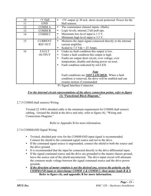
10 +V Hall<br />
11 GND<br />
12 COMM A<br />
13 COMM B<br />
14 COMM C<br />
15 CURRENT<br />
REF OUT<br />
16 FAULT<br />
OUTPUT<br />
• +5V output @ 30 mΑ, short circuit protected. Power for the<br />
Hall sensors.<br />
• The commutator channel inputs (Halls).<br />
• Logic levels, internal 2 kW pull-ups.<br />
• Maximum low-level input is 1.5 V.<br />
• Minimum high level input is 3.5 V.<br />
• Monitors the input signal connected directly to the internal<br />
current amplifier.<br />
• Scaled to 7.5 Vdc = 25 Amps.<br />
• Under no fault condition this output is low.<br />
• Under a fault condition this output is high.<br />
• Faults are output short circuit, over voltage, over<br />
temperature, disable and during power on reset.<br />
• Fault condition indicated by red LED.<br />
Note<br />
Fault conditions are NOT LATCHED. When a fault<br />
condition is removed, the drive will be enabled and can<br />
resume motion if commanded.<br />
P1 Signal Interface Connector<br />
For the internal circuit representations of the above connection points, refer to figure<br />
(1) “Functional Block Diagram.”<br />
2.7.5 COMM (hall sensors) Wiring<br />
Twisted 22 AWG shielded cable is the minimum requirement for COMM (hall sensor)<br />
cabling. Ground the shield at the drive end only; refer to figure (4), “Wiring and<br />
Connections Diagram.”<br />
2.7.6 COMMAND Signal Wiring<br />
Refer to Appendix B for more information.<br />
• Twisted, shielded pair wire for the COMMAND input signal is recommended.<br />
Connect the shield to the command signal source and not to the drive.<br />
• If the command signal source is ungrounded, connect the shield to both the source and<br />
the drive ground.<br />
• It is recommended that the input be connected directly to the drive differential input.<br />
• If the signal command source and the drive are grounded to the master chassis ground,<br />
leave the source end of the shield unconnected. The drive-input circuit will attenuate<br />
the common mode voltage between the signal command source and the drive power<br />
grounds.<br />
• If the direction of motor rotation is not the desired one, reverse the polarity on the<br />
COMMAND input or interchange COMM A & COMM C; then motor leads R & S.<br />
Refer to figure (4), and appendix B for more information.<br />
_______________________________________________________________________________________________<br />
Page - 11 -<br />
MCG Inc. BMC 12H – Hardware Installation