BMC12H-installation-manual.pdf - Servo2Go
BMC12H-installation-manual.pdf - Servo2Go
BMC12H-installation-manual.pdf - Servo2Go

Create successful ePaper yourself
Turn your PDF publications into a flip-book with our unique Google optimized e-Paper software.
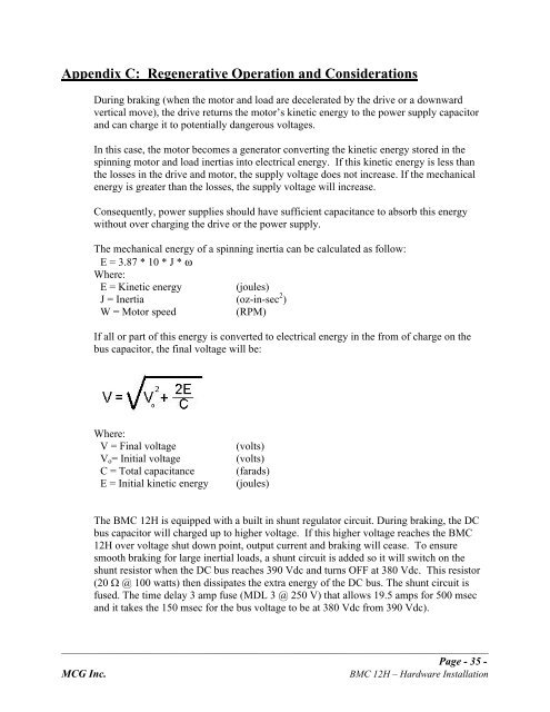
Appendix C: Regenerative Operation and Considerations<br />
During braking (when the motor and load are decelerated by the drive or a downward<br />
vertical move), the drive returns the motor’s kinetic energy to the power supply capacitor<br />
and can charge it to potentially dangerous voltages.<br />
In this case, the motor becomes a generator converting the kinetic energy stored in the<br />
spinning motor and load inertias into electrical energy. If this kinetic energy is less than<br />
the losses in the drive and motor, the supply voltage does not increase. If the mechanical<br />
energy is greater than the losses, the supply voltage will increase.<br />
Consequently, power supplies should have sufficient capacitance to absorb this energy<br />
without over charging the drive or the power supply.<br />
The mechanical energy of a spinning inertia can be calculated as follow:<br />
E = 3.87 * 10 * J * ω<br />
Where:<br />
E = Kinetic energy<br />
(joules)<br />
J = Inertia (oz-in-sec 2 )<br />
W = Motor speed<br />
(RPM)<br />
If all or part of this energy is converted to electrical energy in the from of charge on the<br />
bus capacitor, the final voltage will be:<br />
Where:<br />
V = Final voltage<br />
V o = Initial voltage<br />
C = Total capacitance<br />
E = Initial kinetic energy<br />
(volts)<br />
(volts)<br />
(farads)<br />
(joules)<br />
The BMC 12H is equipped with a built in shunt regulator circuit. During braking, the DC<br />
bus capacitor will charged up to higher voltage. If this higher voltage reaches the BMC<br />
12H over voltage shut down point, output current and braking will cease. To ensure<br />
smooth braking for large inertial loads, a shunt circuit is added so it will switch on the<br />
shunt resistor when the DC bus reaches 390 Vdc and turns OFF at 380 Vdc. This resistor<br />
(20 W @ 100 watts) then dissipates the extra energy of the DC bus. The shunt circuit is<br />
fused. The time delay 3 amp fuse (MDL 3 @ 250 V) that allows 19.5 amps for 500 msec<br />
and it takes the 150 msec for the bus voltage to be at 380 Vdc from 390 Vdc).<br />
_______________________________________________________________________________________________<br />
Page - 35 -<br />
MCG Inc. BMC 12H – Hardware Installation