BMC12H-installation-manual.pdf - Servo2Go
BMC12H-installation-manual.pdf - Servo2Go
BMC12H-installation-manual.pdf - Servo2Go

Create successful ePaper yourself
Turn your PDF publications into a flip-book with our unique Google optimized e-Paper software.
3.3 Torque (current) Mode<br />
The torque (current) mode produces a torque output from the motor proportional to the<br />
COMMAND voltage input signal. The brushless DC servo motor output torque is<br />
proportional to the motor current.<br />
Torque (current) mode is especially important if the servo drive is used with a digital<br />
position controller. Under this condition, a movement of the motor shaft from the desired<br />
position causes a large correcting torque or “stiffness.” Therefore, this mode may produce<br />
a “runaway” condition if operated without a controller.<br />
3.3.1 Torque (current) Mode Setup Procedure<br />
Note<br />
The following setup procedure should be done with the motor unloaded (the load is<br />
uncoupled from the motor shaft)<br />
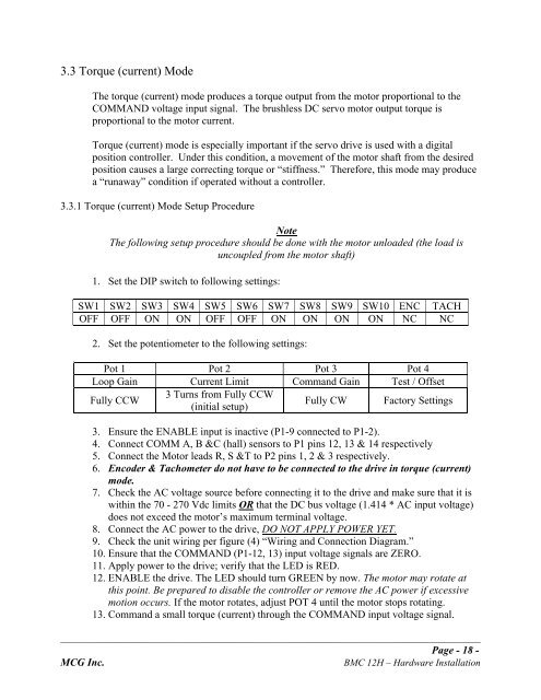
1. Set the DIP switch to following settings:<br />
SW1 SW2 SW3 SW4 SW5 SW6 SW7 SW8 SW9 SW10 ENC TACH<br />
OFF OFF ON ON OFF OFF ON ON ON ON NC NC<br />
2. Set the potentiometer to the following settings:<br />
Pot 1 Pot 2 Pot 3 Pot 4<br />
Loop Gain Current Limit Command Gain Test / Offset<br />
Fully CCW<br />
3 Turns from Fully CCW<br />
(initial setup)<br />
Fully CW Factory Settings<br />
3. Ensure the ENABLE input is inactive (P1-9 connected to P1-2).<br />
4. Connect COMM A, B &C (hall) sensors to P1 pins 12, 13 & 14 respectively<br />
5. Connect the Motor leads R, S &T to P2 pins 1, 2 & 3 respectively.<br />
6. Encoder & Tachometer do not have to be connected to the drive in torque (current)<br />
mode.<br />
7. Check the AC voltage source before connecting it to the drive and make sure that it is<br />
within the 70 - 270 Vdc limits OR that the DC bus voltage (1.414 * AC input voltage)<br />
does not exceed the motor’s maximum terminal voltage.<br />
8. Connect the AC power to the drive, DO NOT APPLY POWER YET.<br />
9. Check the unit wiring per figure (4) “Wiring and Connection Diagram.”<br />
10. Ensure that the COMMAND (P1-12, 13) input voltage signals are ZERO.<br />
11. Apply power to the drive; verify that the LED is RED.<br />
12. ENABLE the drive. The LED should turn GREEN by now. The motor may rotate at<br />
this point. Be prepared to disable the controller or remove the AC power if excessive<br />
motion occurs. If the motor rotates, adjust POT 4 until the motor stops rotating.<br />
13. Command a small torque (current) through the COMMAND input voltage signal.<br />
_______________________________________________________________________________________________<br />
Page - 18 -<br />
MCG Inc. BMC 12H – Hardware Installation