BMC12H-installation-manual.pdf - Servo2Go
BMC12H-installation-manual.pdf - Servo2Go
BMC12H-installation-manual.pdf - Servo2Go

Create successful ePaper yourself
Turn your PDF publications into a flip-book with our unique Google optimized e-Paper software.
3.2.2 CURRENT LIMIT, “POT 2” ADJUSTMENT<br />
It is critical to set the current limit so that the instantaneous motor current does not exceed<br />
the specified motor peak current ratings. Should this occur, the motor may be<br />
demagnetized. This would reduce both the torque constant and the torque rating of the<br />
motor and seriously affect the system performance.<br />
MCG servo drives feature peak and continuous current limit adjustments. The maximum<br />
peak current is needed for fast acceleration and deceleration. This drive is capable of<br />
supplying the maximum peak current for 2 seconds and then the current limit is reduced<br />
gradually to the continuous value.<br />
The purpose of this is to protect the motor in stalled condition by reducing the current limit<br />
to the maximum continuous value. Current limiting is done in the drive by reducing the<br />
output voltage to the motor.<br />
The current limit adjustment potentiometer, “POT 2,” has one inactive turn at each end and<br />
is approximately linear. Thus, to adjust the current limit, turn POT 2 CCW to zero then<br />
turn it CW to the appropriate setting.<br />
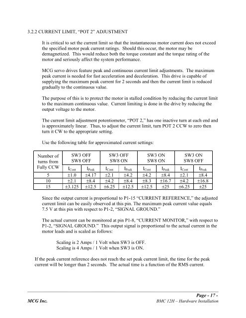
Use the following table for approximated current settings:<br />
Number of<br />
turns from<br />
Fully CCW ICont I Peak I Cont I Peak I Cont I Peak I Cont I Peak<br />
5 !1.0 !4.17 !2.1 !4.2 !4.2 !8.4 !2.1 !8.4<br />
10 !2.1 !8.4 !4.2 !8.4 !8.3 !16.7 !4.2 !16.8<br />
15 !3.125 !12.5 !6.25 !12.5 !12.5 !25 !6.25 !25<br />
SW3 OFF<br />
SW8 OFF<br />
SW3 OFF<br />
SW8 ON<br />
SW3 ON<br />
SW8 ON<br />
SW3 ON<br />
SW8 OFF<br />
Since the output current is proportional to P1-15 “CURRENT REFERENCE,” the adjusted<br />
current limit can be easily observed at this pin. The maximum peak current value equals<br />
7.5 V at this pin with respect to P1-2, “SIGNAL GROUND.”<br />
The actual current can be monitored at pin P1-8, “CURRENT MONITOR,” with respect to<br />
P1-2, “SIGNAL GROUND.” This output signal is proportional to the actual current in the<br />
motor leads and is scaled as follows:<br />
Scaling is 2 Amps / 1 Volt when SW3 is OFF.<br />
Scaling is 4 Amps / 1 Volt when SW3 is ON.<br />
If the peak current reference does not reach the set peak current limit, the time for the peak<br />
current will be longer than 2 seconds. The actual time is a function of the RMS current.<br />
_______________________________________________________________________________________________<br />
Page - 17 -<br />
MCG Inc. BMC 12H – Hardware Installation