Hep20 Technical Handbook
Hep20 Technical Handbook
Hep20 Technical Handbook

You also want an ePaper? Increase the reach of your titles
YUMPU automatically turns print PDFs into web optimized ePapers that Google loves.
2. Fix each conduit pipe to noggins<br />
using suitable straps or cable<br />
ties. Fixings at 1m centres are<br />
adequate for vertical conduit<br />
pipe. Horizontal runs and bends<br />
more than 45° should be<br />
avoided.<br />
3. To allow future installation of<br />
drylining boxes, each conduit<br />
pipe end should be left<br />
approximately 100mm longer<br />
than box position and should<br />
not be fixed closer than 600mm<br />
to the box.<br />
4. Install the main ‘first-fix’<br />
pipework leaving joints below<br />
floor access covers to allow<br />
connection to conduit pipework<br />
during ‘second fix’ work.<br />
5. Using setting-out dimensions on<br />
sketches, holes in plasterboard<br />
can be cut to allow each conduit<br />
pipe to be pulled out through<br />
the surface during plasterboard<br />
fixing work.<br />
6. During ‘second fix’ each dry<br />
lining box is installed by drilling a<br />
26mm diameter hole for 15mm<br />
(nominal) conduit pipe. The<br />
conduit can then be inserted<br />
through hole in box and should<br />
‘click’ into position leaving one<br />
or two conduit ‘ribs’ inside box.<br />
7. Slide a length of 10mm Hep 2 O ®<br />
pipe through conduit pipe from<br />
the floor access above. Pull out<br />
enough Hep 2 O ® from drylining<br />
box to allow a sufficient hand<br />
grip for jointing. Connect a<br />
demountable elbow to pipe then<br />
slide whole assembly through<br />
plasterboard hole and secure<br />
box into position. Conduit pipe<br />
should ‘snake’ within void to<br />
take up slack leaving Hep 2 O ®<br />
protruding out of box.<br />
8. Pull Hep 2 O ® pipe backwards<br />
from floor access panel until<br />
elbow is central within dry lining<br />
box. Cut pipe to length and<br />
connect to Hep 2 O ® joint left<br />
during ‘first fix’.<br />
General advice on timber or<br />
steel framed buildings<br />
Holes through timber joists should<br />
be drilled in accordance with<br />
Figures 16 & 17, on page 65. Holes<br />
through timber studs should be<br />
drilled in accordance with Figure 30.<br />
Within steel framed buildings<br />
pipework should be routed through<br />
preformed holes in steelwork<br />
wherever practicable (and where<br />
provided). No holes should be<br />
formed in steelwork without the<br />
approval of the Architect. Pipework<br />
passing through steelwork should be<br />
protected from damage. Refer to<br />
‘Pipes Through, and Adjacent to,<br />
Metalwork’ on page 69. Do not lay<br />
pipework in areas where<br />
plasterboard is likely to be fixed.<br />
Services within compartment or<br />
party walls should be avoided so as<br />
not to impair fire resistance or<br />
acoustic properties.<br />
Care should be taken that pipework<br />
passing through compartment<br />
walls or floors does not impair the<br />
fire resistance of the property.<br />
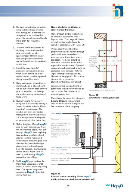
10mm Hep 2 O ®<br />
Plasterboard<br />
15mm (nominal) Conduit Pipe<br />
firmly terminated within<br />
drylining box<br />
(When cutting vapour control<br />
plasterboard around drylining<br />
box, care should be taken not<br />
to displace vapour control<br />
material)<br />
100mm Hep 2 O ® Single Socket<br />
SlimLine Elbow (HX4/10)<br />
Demountable Elbow (HD5/10)<br />
Drylining box and cover plate<br />
(single gang electrical fitting)<br />
Insulation<br />
Holes should<br />
be located in<br />
these zones<br />
and drilled at<br />
centre of<br />
stud depth<br />
Figure 29<br />
Radiator connection using 10mm Hep 2 O ®<br />
within a timber or steel framed external wall<br />
0.25 x H<br />
Figure 30<br />
Limitations of drilling studwork<br />
D<br />
0.25 x H<br />
Max dia of holes = 0.25 depth of stud ‘D’<br />
0.4 x H<br />
Stud height ‘H’<br />
0.4 x H<br />
79