T 7.2.1.3 Amplitude Modulation
T 7.2.1.3 Amplitude Modulation
T 7.2.1.3 Amplitude Modulation

Create successful ePaper yourself
Turn your PDF publications into a flip-book with our unique Google optimized e-Paper software.
TPS <strong>7.2.1.3</strong><br />
Introduction<br />
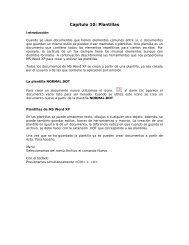
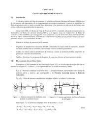
Harmonic Frequency <strong>Amplitude</strong><br />
1<br />
2<br />
3<br />
4<br />
n<br />
f R = 1/T R SR(1)= 4 A<br />
π<br />
3 f R<br />
5 f R<br />
7 f R<br />
(2 n – 1) f R<br />
S R (1)<br />
3<br />
S R (1)<br />
5<br />
S R (1)<br />
7<br />
SR (1)<br />
2n<br />
−1<br />
<strong>Amplitude</strong> spectrum of a symmetrical squarewave<br />
signal n = 1, 2, 3, 4, ...<br />
ion. Either harmonic oscillations or pulse trains<br />
are used as carrier signals. If, for example, a harmonic<br />
carrier is used with the form:<br />
s C<br />
(t) = A C<br />
cos (2 f C<br />
t + φ ), (1.3)<br />
then the message signal s M (t) can have an effect<br />
either on the amplitude A C , the carrier frequency<br />
f C or the zero phase angle φ. These effects result in<br />
the analog modulation methods:<br />
– <strong>Amplitude</strong> modulations (AM)<br />
– Frequency modulation (FM)<br />
– Phase modulation (PM).<br />
In the case of analog modulation methods, the<br />
modulation process means a continuous conversion<br />
of the modulating signal s M (t) into a higher<br />
frequency band (frequency conversion). The mod-<br />
R<br />
ulating signal is shifted from the baseband (AF<br />
range, original frequency band), into an RF frequency<br />
band. It no longer appears in the spectrum<br />
of the modulated oscillation. A modulation always<br />
requires that the carrier and the modulation<br />
signal interact. Both of these signals are fed into a<br />
modulator. The original signal s M (t) is recovered<br />
from the modulated signal through demodulation.<br />
Consequently, modulation and demodulation are<br />
mutually related, inverse processes. The complexities<br />
involved in modulation and demodulation are<br />
considerable. The following reasons explain why<br />
modulation is worthwhile:<br />
1. <strong>Modulation</strong> enables the matching of the<br />
modulating signal to the characteristics of the<br />
transmission channel. (radio links e.g. are<br />
only possible above a certain frequency.)<br />
2. Existing transmission channels can be multiply<br />
exploited using modulation, (frequency<br />
or time division multiplex systems).<br />
3. Improved signal-to-noise ratios can be obtained<br />
using modulation.<br />
The communications system according to Shannon<br />
Electrical communications engineering is divided<br />
into three classical subfunctions:<br />
1. Transmission of the message<br />
2. Processing of the message<br />
3. Relaying the message (telephone technology)<br />
If only a single transmission channel is examined,<br />
(i.e. no telephone technology), then we can concentrate<br />
on the remaining functions illustrated by<br />
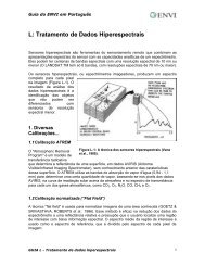
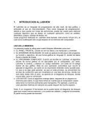
the scheme in Fig. 1-3.<br />
Fig. 1-3: The telecommunications system<br />
(A) The telecommunications system<br />
(B) Message transmission<br />
(C) Message processing<br />
1 Message source<br />
(human being, measurment sensor etc.)<br />
2 Converter (microphone,<br />
television camera,<br />
strain gauges, thermo sensor etc.)<br />
3 Transmitter<br />
4 Transmission channel (radio link,<br />
transmission cable, data storage system)<br />
5 Receiver<br />
6 Converter<br />
7 Message recipient<br />
8 Interference source<br />
11