T 7.2.1.3 Amplitude Modulation
T 7.2.1.3 Amplitude Modulation
T 7.2.1.3 Amplitude Modulation

You also want an ePaper? Increase the reach of your titles
YUMPU automatically turns print PDFs into web optimized ePapers that Google loves.
TPS <strong>7.2.1.3</strong><br />
Solutions<br />
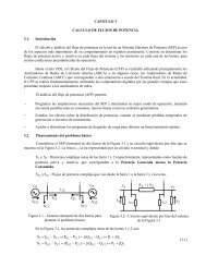
5.3.3 DSB SC<br />
demodulation<br />
Table 5.4-1: Spectrum of a beat<br />
Signal parameter<br />
Analyzer settings<br />
A 2 : 2 V V 1 : 5<br />
f 2 : 20.0 kHz b : 500 Hz<br />
f r : 50 kHz<br />
A 1 : 2 V T : 20 s<br />
f 1 : 2 kHz SPAN: 1...25 kHz<br />
Diagram 5.3.3-1: Modulating and demodulated signal for<br />
DSB SC<br />
(1): Demodulated signal s D<br />
(t)<br />
(2): Modulating signal s M<br />
(t)<br />
The DSB SC shows the same phase-dependency as<br />
the DSB<br />
Requirements for the auxiliary carrier in synchronous<br />
demodulation:<br />
1. Frequency stability and frequency equality<br />
with the original carrier frequency.<br />
2. Constant phase angle < 90°. Ideally φ€= 0°.<br />
3. <strong>Amplitude</strong> stability of the auxiliary carrier<br />
n<br />
f<br />
KHz<br />
Measurement<br />
Name<br />
S( n)<br />
V2<br />
S AM (n)<br />
Theory<br />
1 2 10.5 2.1 2<br />
1 20 10.5 2.1 2<br />
V<br />
S AM (n)<br />
V<br />
5.4 Beats<br />
Diagram 5.4-2: Spectrum of the beat<br />
Diagram 5.4-1: Additive superpositioning of 2 sinusoidal<br />
signals with the same amplitudes but very different<br />
frequencies.<br />
Linear superpositioning of 2 harmonic signals, here<br />
with extremely different frequencies f 1 = 2.0 kHz<br />
and f 2 = 20 kHz, generates a beat. The two<br />
frequency components are easily distinguishable.<br />
There is no frequency conversion for beats<br />
Diagram 5.4-3: Additive superimposing of 2 sinusoidal<br />
signals with the same amplitudes and almost the same<br />
frequencies.<br />
58