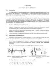
T 7.2.1.3 Amplitude Modulation
T 7.2.1.3 Amplitude Modulation
T 7.2.1.3 Amplitude Modulation

Create successful ePaper yourself
Turn your PDF publications into a flip-book with our unique Google optimized e-Paper software.
TPS <strong>7.2.1.3</strong><br />
Review<br />
t = t 1<br />
s AM<br />
USL<br />
USL<br />
t = t 2<br />
LSL<br />
LSL<br />
s C<br />
s C<br />
s AM<br />
Fig. 3-6: <strong>Amplitude</strong> modulation in a vector diagram Fig. 3-7: Relationship between envelope and vector<br />
representation<br />
1. The carrier oscillation is depicted with a constant<br />
direction (normally perpendicular upwards),<br />
although in absolute terms it rotates in<br />
counterclockwise rotation with 2 π f C .<br />
2. The length of the carrier vector remains constant.<br />
3. The sideband vectors are symmetrical with<br />
respect to the carrier. The vector of the USL<br />
rotates counterclockwise around the tip of the<br />
carrier vector. The vector of the LSL rotates<br />
in clockwise rotation.<br />
4. The vector for the amplitude modulated oscillation<br />
is obtained through vector addition, i.e.<br />
construction of the vector parallelogram,<br />
made up of the vector of the carrier and the<br />
side oscillations. The resulting vector always<br />
has the direction of the carrier vector.<br />
As you can see from Fig. 3-7, the tips of the resulting<br />
vectors, if you draw them as a function of time,<br />
again produce the envelope of the amplitude<br />
modulated oscillation.<br />
1. A DC voltage component<br />
2. The original signal with the frequency f M .<br />
3. Components with higher frequencies f C ,<br />
f C + f M , 2 f C + f M , etc.<br />
Fourier expansion shows that rectification of the<br />
AM signal produces many new spectral components<br />
which are not present at the input of the rectifier.<br />
A suitable filter is used to suppress these<br />
unwanted spectral components. Envelope demodulation<br />
belongs to the so-called incoherent<br />
demodulation methods, as neither the carrier phase<br />
nor the carrier frequency are of any importance.<br />
Fig. 3-9 reproduces the possible circuit configuration<br />
of an envelope demodulator.<br />
AM demodulation<br />
Envelopes and synchronous demodulation<br />
1st envelope demodulation<br />
First the AM signal is rectified, see Fig. 3-8.<br />
The dynamic characteristic of the current passing<br />
through the recifier can be subjected to Fourier<br />
series expansion. It can be shown that a rectified<br />
AM signal contains the following signal components:<br />
Fig. 3-8: Envelope curve demodulation<br />
25