T 7.2.1.3 Amplitude Modulation
T 7.2.1.3 Amplitude Modulation
T 7.2.1.3 Amplitude Modulation

You also want an ePaper? Increase the reach of your titles
YUMPU automatically turns print PDFs into web optimized ePapers that Google loves.
TPS <strong>7.2.1.3</strong><br />
Solutions<br />
5.3.2 Carrier recovery<br />
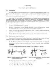
Table 5.3.2-1:<br />
Control characteristic of the VCO<br />
U F<br />
V<br />
f VCO<br />
kHz<br />
0.5 0.0<br />
corresponds precisely to the frequency difference<br />
between the carrier and the auxiliary oscillation.<br />
The frequency shift in the demodulated signal disappears<br />
completely for f C = f Aux .<br />
Synchronous demodulation with the aid of a<br />
PLL-controlled VCO.<br />
1.0 0.0<br />
1.5 0.3<br />
2.0 14.5<br />
2.5 41.3<br />
3.0 69.1<br />
3.5 96.3<br />
4.0 121.8<br />
4.5 148.7<br />
5.0 167.5<br />
Diagram 5.3.2-2:<br />
(1): Pilot tone at the CF transmitter<br />
(2): Recovered pilot at the output of the PLL (receiver)<br />
After lock-in of the PLL the original pilot signal<br />
and the recovered signal have exactly the same<br />
frequency. A fixed phase-shift occurs between<br />
the two signals. This leads to a (constant)<br />
amplitude error during synchronous demodulation.<br />
Diagram 5.3.2-1: The control characteristic of the VCO in<br />
the PLL circuit of the receiver<br />
The synchronous demodulation is performed<br />
with the aid of a free-wheeling VCO.<br />
In the demodulated signal a constant frequency<br />
shift occurs for f C ≈ f Aux . This is maintained during<br />
variation of the signal frequency f M . It is only dependent<br />
on the control voltage U F of the VCO,<br />
which determines the frequency f Aux of the auxiliary<br />
carrier. The frequency phase-shift between<br />
the modulating signal and the demodulated signal<br />
Diagram 5.3.2-3:<br />
(1): 20 kHz original carrier at the transmitter<br />
(2): The recovered auxiliary carrier at the receiver<br />
A fixed phase-shift exists between the two carriers.<br />
This phase-shift can assume 8 various values<br />
due to the undefined starting conditions of the frequency<br />
divider (f/8). These phase-shifts are associated<br />
with amplitude errors in the demodulated<br />
signal.<br />
57