T 7.2.1.3 Amplitude Modulation
T 7.2.1.3 Amplitude Modulation
T 7.2.1.3 Amplitude Modulation

Create successful ePaper yourself
Turn your PDF publications into a flip-book with our unique Google optimized e-Paper software.
TPS <strong>7.2.1.3</strong><br />
Ring Modulator<br />
s M<br />
i<br />
i<br />
C<br />
2<br />
C<br />
2<br />
^↑Φ<br />
^↓Φ<br />
T / 2<br />
T / 2<br />
⎫<br />
⎪<br />
⎪<br />
⎬ΣΦ<br />
⎪<br />
⎪<br />
⎭<br />
C<br />
Φ C Φ<br />
=+ −<br />
2 2<br />
C<br />
! 0<br />
0<br />
f T<br />
3 f T<br />
5 f T f<br />
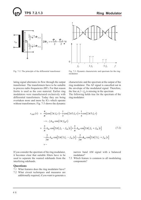
Fig. 7-2: The principle of the differential transformer<br />
Fig. 7-3: Dynamic characteristic and spectrum for the ring<br />
modulator<br />
lating signal alternates its flow through the output<br />
transformer. The transformers have to be suitable<br />
to process radio frequencies (RF). For that reason<br />
ferrite is used as the core material. Earlier ring<br />
modulators were manufactured exclusively with<br />
differential transformers. Today they are being<br />
overtaken more and more by ICs which operate<br />
without transformers. Fig. 7-3 shows the dynamic<br />
characteristic and the spectrum at the output of the<br />
ring modulator. The AF signal is cancelled out in<br />
the envelope of the modulated signal. Therefore,<br />
the line at f = f M is missing in the spectrum<br />
The following holds true for the spectrum of the<br />
ring modulator:<br />
4<br />
1<br />
1<br />
sAM t [cos 2π fCt cos 2π3fCt cos 2π5fCt<br />
π<br />
3<br />
5<br />
( ) = ( ) − ( ) + ( )<br />
−+ ...] A cos( 2π<br />
f t)<br />
M<br />
M<br />
2<br />
2<br />
= AM cos[ 2π<br />
( fC − fM ) t]+ AM cos 2π<br />
( fC + fM<br />
) t<br />
π<br />
π<br />
[ ]<br />
2<br />
2<br />
− AM cos[ 2π<br />
( 3fC − fM<br />
) t]−<br />
AM cos 2π ( 3 fC + fM<br />
) t<br />
3π<br />
3π<br />
+−<br />
[ ]<br />
(7-2)<br />
If you consider the spectrum of the ring modulator,<br />
it becomes clear that suitable filters have to be<br />
used to separate the wanted sidebands from the<br />
interfering sidebands.<br />
Questions<br />
7.1 What features does the ring modulator have?<br />
7.2 What circuit techniques and measures are<br />
additionally required, if you want to generate a<br />
narrow band AM signal with a balanced<br />
modulator?<br />
7.3 Which feature is common to all modulating<br />
components?<br />
48