

Vigilohm System - engineering site - Schneider Electric
Vigilohm System - engineering site - Schneider Electric
Vigilohm System - engineering site - Schneider Electric

Create successful ePaper yourself
Turn your PDF publications into a flip-book with our unique Google optimized e-Paper software.
<strong>Vigilohm</strong>: presentation<br />
<strong>Vigilohm</strong> <strong>System</strong>:<br />
choosing the system architecture<br />
what devices make up the<br />
system?<br />
c XM200 and XM300C insulation monitoring<br />
devices inject a signal that is used by the<br />
detection and locating devices;<br />
c XL308 and XL316 locators, connected to 8<br />
or 16 toroids, measure the insulation<br />
resistance of each circuit (distributed<br />
measurements) and, in the event of a fault,<br />
automatically identify the faulty circuit.<br />
They can transmit this information to a<br />
supervisor;<br />
c XML308 and XML316 monitoring-locating<br />
devices combine the monitoring and locating<br />
functions in a single unit;<br />
c the XD308C communicating insulation<br />
fault detector automatically identifies the<br />
faulty circuit and transmits this information to<br />
a supervisor;<br />
c XD301 and XD312 non-communicating<br />
insulation fault detectors automatically<br />
identify the faulty circuit;<br />
c the XRM mobile receiver can be used to<br />
fine-tune the automatic locating results by<br />
identifying the faulty circuit at the final<br />
distribution level;<br />
c XLI200, XLI300 and XTU300 interfaces<br />
make communication possible between the<br />
<strong>Vigilohm</strong> <strong>System</strong> and a supervisor;<br />
c the XAS interface is used to supply power<br />
to the communication bus.<br />
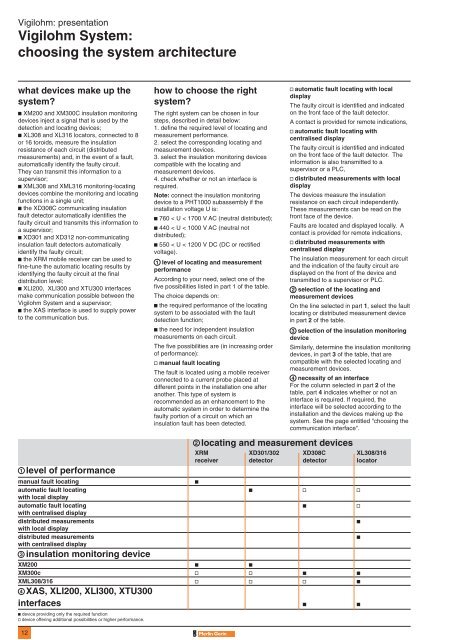
1 level of performance<br />
12<br />
2 locating and measurement devices<br />
XRM XD301/302 XD308C XL308/316<br />
receiver detector detector locator<br />
manual fault locating<br />
c<br />
automatic fault locating c v v<br />
with local display<br />
automatic fault locating c v<br />
with centralised display<br />
distributed measurements<br />
c<br />
with local display<br />
distributed measurements<br />
c<br />
with centralised display<br />
3 insulation monitoring device<br />
XM200 c c<br />
XM300c v v c c<br />
XML308/316 v v v c<br />
4 XAS, XLI200, XLI300, XTU300<br />
interfaces c c<br />
c device providing only the required function<br />
v device offering additional possibilities or higher performance.<br />
how to choose the right<br />
system?<br />
The right system can be chosen in four<br />
steps, described in detail below:<br />
1. define the required level of locating and<br />
measurement performance.<br />
2. select the corresponding locating and<br />
measurement devices.<br />
3. select the insulation monitoring devices<br />
compatible with the locating and<br />
measurement devices.<br />
4. check whether or not an interface is<br />
required.<br />
Note: connect the insulation monitoring<br />
device to a PHT1000 subassembly if the<br />
installation voltage U is:<br />
c 760 < U < 1700 V AC (neutral distributed);<br />
c 440 < U < 1000 V AC (neutral not<br />
distributed);<br />
c 550 < U < 1200 V DC (DC or rectified<br />
voltage).<br />
1 level of locating and measurement<br />
performance<br />
According to your need, select one of the<br />
five possibilities listed in part 1 of the table.<br />
The choice depends on:<br />
c the required performance of the locating<br />
system to be associated with the fault<br />
detection function;<br />
c the need for independent insulation<br />
measurements on each circuit.<br />
The five possibilities are (in increasing order<br />
of performance):<br />
v manual fault locating<br />
The fault is located using a mobile receiver<br />
connected to a current probe placed at<br />
different points in the installation one after<br />
another. This type of system is<br />
recommended as an enhancement to the<br />
automatic system in order to determine the<br />
faulty portion of a circuit on which an<br />
insulation fault has been detected.<br />
v automatic fault locating with local<br />
display<br />
The faulty circuit is identified and indicated<br />
on the front face of the fault detector.<br />
A contact is provided for remote indications,<br />
v automatic fault locating with<br />
centralised display<br />
The faulty circuit is identified and indicated<br />
on the front face of the fault detector. The<br />
information is also transmitted to a<br />
supervisor or a PLC,<br />
v distributed measurements with local<br />
display<br />
The devices measure the insulation<br />
resistance on each circuit independently.<br />
These measurements can be read on the<br />
front face of the device.<br />
Faults are located and displayed locally. A<br />
contact is provided for remote indications,<br />
v distributed measurements with<br />
centralised display<br />
The insulation measurement for each circuit<br />
and the indication of the faulty circuit are<br />
displayed on the front of the device and<br />
transmitted to a supervisor or PLC.<br />
2 selection of the locating and<br />
measurement devices<br />
On the line selected in part 1, select the fault<br />
locating or distributed measurement device<br />
in part 2 of the table.<br />
3 selection of the insulation monitoring<br />
device<br />
Similarly, determine the insulation monitoring<br />
devices, in part 3 of the table, that are<br />
compatible with the selected locating and<br />
measurement devices.<br />
4 necessity of an interface<br />
For the column selected in part 2 of the<br />
table, part 4 indicates whether or not an<br />
interface is required. If required, the<br />
interface will be selected according to the<br />
installation and the devices making up the<br />
system. See the page entitled "choosing the<br />
communication interface".


