

Vigilohm System - engineering site - Schneider Electric
Vigilohm System - engineering site - Schneider Electric
Vigilohm System - engineering site - Schneider Electric

Create successful ePaper yourself
Turn your PDF publications into a flip-book with our unique Google optimized e-Paper software.
DB100954<br />
locator XL308 XL316<br />
electrical characteristics<br />
ohmmeter<br />
digital<br />
range for insulation resistance readings<br />
0.1 to 999 kΩ<br />
signalling 8 lights (1 per channel) 16 lights (1 per channel)<br />
signalling threshold and 1<br />
setting range (per channel) fault threshold 0.2 to 99.9 kΩ<br />
polling time<br />
15 seconds per channel<br />
device test<br />
self-test and manual test<br />
dielectric strength<br />
2500 V<br />
auxiliary supply voltage 50/60 Hz 115/127 V AC<br />
220/240 V AC<br />
380/415 V AC<br />
500/525 V AC<br />
auxiliary supply voltage tolerances - 15 % to + 10 %<br />
maximum device consumption<br />
30 VA<br />
indicator and output relay<br />
local or from insulation monitoring device<br />
output relays<br />
2 (1 failsafe)<br />
breaking capacity of<br />
output contacts<br />
AC 400 V p.f. = 0.7<br />
230 V p.f. = 0.7<br />
3 A<br />
5 A<br />
DC 220 V L/R = 1 ms<br />
0.45 A<br />
120 V L/R = 1 ms 0.65 A<br />
48 V L/R = 1 ms 2.5 A<br />
24 V L/R = 1 ms 10 A<br />
link with insulation monitoring device<br />
via 4-wire communication bus<br />
connection crosssections<br />
mechanical characteristics<br />
weight<br />
sheet-metal case<br />
other characteristics<br />
(1) The upper limit is extended to the second value by adding a PTH1000 subassembly.<br />
The same voltage limits apply to both the XL308 and the XL316.<br />
rigid conductors 1 to 1.5 mm 2<br />
flexible conductors 0.75 to 1.5 mm 2<br />
3.5 kg<br />
horizontal mounting<br />
disconnectable screw terminal block<br />
types of toroid to be used<br />
A and OA (XC compatible)<br />
temperature range operating - 5 °C to + 55 °C<br />
storage - 20 °C to + 70 °C<br />
MERLIN GERIN<br />
XL31<br />
6<br />
-<br />
∝<br />
+<br />
1 2 3 4 5 6 7 8<br />
9 10 1 12 13 14 15 16<br />
1<br />
∝F !<br />
/<br />
test/rese<br />
t<br />
1 2 9 7 8 5 6 4 3<br />
i<br />
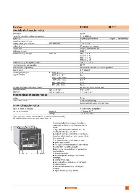
1. display indicating measured insulation<br />
resistance and earth coupling capacitance<br />
value.<br />
2. light indicating measurement units for<br />
displayed value (kΩ, µF, etc.).<br />
3. red self-test light, indicating device faults.<br />
4. yellow light indicating that a transient fault<br />
has occurred.<br />
5. 2 lights indicating the insulation level:<br />
c green light: normal;<br />
c red light: insulation resistance below fault<br />
threshold on one of the circuits.<br />
6. instruction manual stored in a drawer on<br />
the front face<br />
7. function keys for:<br />
c accessing earth leakage capacitance<br />
readings;<br />
c setting thresholds;<br />
c accessing three last values of transient<br />
insulation faults.<br />
8. sealable cover ensuring tamperproof<br />
settings.<br />
9. lights indicating faulty circuits.<br />
25


