

Vigilohm System - engineering site - Schneider Electric
Vigilohm System - engineering site - Schneider Electric
Vigilohm System - engineering site - Schneider Electric

You also want an ePaper? Increase the reach of your titles
YUMPU automatically turns print PDFs into web optimized ePapers that Google loves.
auxiliaries<br />
Cardew surge limiter: page 43.<br />
ZX limiting impedance to create an<br />
impedance-earthed neutral: page 44.<br />
PHT1000 subassembly if the device is to<br />
be used on 1000-1700 V installations:<br />
page 44.<br />
restrictions for use<br />
The XM300C operates by injecting lowfrequency<br />
signals (2.5 Hz). It should not be<br />
used for circuits that include variable speed<br />
drives if this equipment continuously<br />
generates a signal with a similar frequency<br />
(≤ 5 Hz).<br />
E19527<br />
MERLIN GERIN<br />
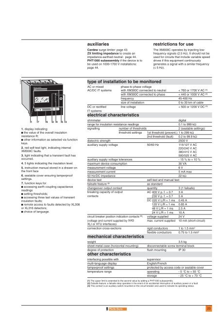
XM300C<br />
1 7 6 2 4 5 3<br />
1. display indicating:<br />
c the value of the overall insulation<br />
resistance R;<br />
c other information as selected via function<br />
keys.<br />
2. red self-test light, indicating internal<br />
XM300C faults.<br />
3. light indicating that a transient fault has<br />
occurred.<br />
4. 5 lights indicating the insulation level.<br />
5. instruction manual stored in a drawer on<br />
the front face<br />
6. sealable cover ensuring tamperproof<br />
settings.<br />
7. function keys for:<br />
c accessing earth coupling capacitance<br />
readings<br />
c setting thresholds;<br />
c accessing three last values of transient<br />
insulation faults;<br />
c remote access to faults detected by XL308<br />
or XL316 detectors;<br />
c choice of language.<br />
test<br />
i<br />
type of installation to be monitored<br />
AC or mixed<br />
phase-to phase voltage<br />
AC/DC IT systems with XM300C connected to neutral < 760 or 1700 V AC (1)<br />
with XM300C connected to phase < 440 or 1000 V AC (1)<br />
frequency<br />
45-400 Hz<br />
size of installation<br />
0 to 30 km of cable<br />
DC or rectified line voltage < 500 or 1200 V DC (1)<br />
IT systems<br />
electrical characteristics<br />
ohmmeter<br />
digital<br />
range for insulation resistance readings<br />
0.1 to 999 kΩ<br />
signalling number of thresholds 2 (sealable settings)<br />
threshold settings 1st threshold (prevent.) 1 to 299 kΩ<br />
2nd threshold (fault) 0.2 to 99.9 kΩ<br />
dielectric strength<br />
2500 V<br />
auxiliary supply voltage 50/60 Hz 115/127 V AC<br />
220/240 V AC<br />
380/415 V AC<br />
500/525 V AC<br />
auxiliary supply voltage tolerances - 15 % to + 10 %<br />
maximum device consumption<br />
30 VA<br />
measurement voltage<br />
6 V<br />
measurement current<br />
5 mA max<br />
50 Hz/DC impedance 22 kΩ<br />
device test<br />
self-test and manual test<br />
failsafe feature (2)<br />
as standard<br />
changeover output contact quantity 3 (1 failsafe)<br />
breaking capacity of output AC 400 V p. f. = 0.7 3 A<br />
contacts 230 V p. f. = 0.7 5 A<br />
DC 220 V L/R = 1 ms 0.45 A<br />
120 V L/R = 1 ms 0.65 A<br />
48 V L/R = 1 ms 2.5 A<br />
24 V L/R = 1 ms 10 A<br />
circuit breaker position indication contacts (3) : voltage supplied 24 V<br />
(voltage and current supplied by XAS max. current supplied 10 mA (short-circuit)<br />
XLI or XTU interfaces)<br />
connection cross-sections rigid conductors 1 to 1.5 mm 2<br />
flexible conductors 0.75 to 1.5 mm 2<br />
mechanical characteristics<br />
weight<br />
sheet-metal case (horizontal mounting)<br />
3.5 kg<br />
disconnectable screw terminal block<br />
degree of protection flush mounting IP 30<br />
other characteristics<br />
interfacing possible with<br />
supervisor<br />
multi-language display<br />
English/French<br />
tamperproof settings<br />
protected by access code or sealable cover<br />
temperature range operating - 5 °C to + 55 °C<br />
storage - 25 °C to + 70 °C<br />
(1) The upper limit is extended to the second value by adding a PHT1000 subassembly.<br />
(2) Failsafe feature: a failsafe relay operates in the event of an accidental interruption of auxiliary power or a fault.<br />
(3) This contact is an auxiliary switch mounted on the circuit breaker and used to indicate its operating status.<br />
23


