KR QUANTEC ultra - KUKA Robotics
KR QUANTEC ultra - KUKA Robotics
KR QUANTEC ultra - KUKA Robotics

You also want an ePaper? Increase the reach of your titles
YUMPU automatically turns print PDFs into web optimized ePapers that Google loves.
<strong>KR</strong> <strong>QUANTEC</strong> <strong>ultra</strong><br />
Supplementary load on rotating column<br />
Supplementary load on base frame<br />
On request<br />
On request<br />
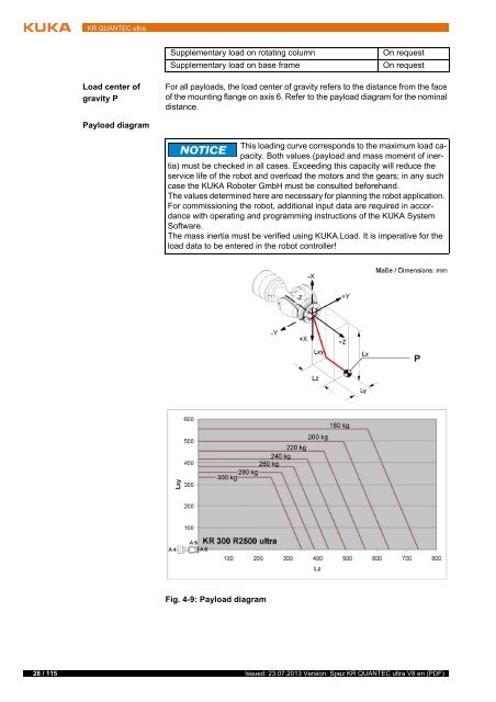
Load center of<br />
gravity P<br />
For all payloads, the load center of gravity refers to the distance from the face<br />
of the mounting flange on axis 6. Refer to the payload diagram for the nominal<br />
distance.<br />
Payload diagram<br />
This loading curve corresponds to the maximum load capacity.<br />
Both values (payload and mass moment of inertia)<br />
must be checked in all cases. Exceeding this capacity will reduce the<br />
service life of the robot and overload the motors and the gears; in any such<br />
case the <strong>KUKA</strong> Roboter GmbH must be consulted beforehand.<br />
The values determined here are necessary for planning the robot application.<br />
For commissioning the robot, additional input data are required in accordance<br />
with operating and programming instructions of the <strong>KUKA</strong> System<br />
Software.<br />
The mass inertia must be verified using <strong>KUKA</strong>.Load. It is imperative for the<br />
load data to be entered in the robot controller!<br />
Fig. 4-9: Payload diagram<br />
28 / 115 Issued: 23.07.2013 Version: Spez <strong>KR</strong> <strong>QUANTEC</strong> <strong>ultra</strong> V8 en (PDF)