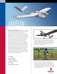
Piccolo system user guide - Unmanned Aircraft & Drones
Piccolo system user guide - Unmanned Aircraft & Drones
Piccolo system user guide - Unmanned Aircraft & Drones

You also want an ePaper? Increase the reach of your titles
YUMPU automatically turns print PDFs into web optimized ePapers that Google loves.
Clo ud Cap<br />
Technology<br />
PO Box 1500, No. 8 Fourth St, Hood River, OR 97031, ph 541 387 2120, fax 541 387 2030<br />
2.7 Communications antenna<br />
A 900MHz or 2.4GHz ISM band ¼ wave or similar antenna will need to be installed on the host<br />
airframe. You should try to maximize the separation between the GPS and UHF antennas to<br />
minimize potential interference. Again refer to the “Vehicle Integration Guidelines” document<br />
for examples and further details.<br />
3 Ground Station<br />
<strong>Piccolo</strong>’s ground station is based upon the same hardware that makes up the avionics package. It<br />
manages the communication link to one or more avionics <strong>system</strong>s, interfaces to the pilot in the<br />
loop console, and provides a command and control stream to the operator interface PC.<br />
3.1 Power<br />
The ground station is powered through the included power supply that provides DC power. A<br />
battery is included in the ground station for backup operation in case the main input power is<br />
lost. When main power is connected the battery will be charging (Yellow LED). The ground<br />
station will not be on until the external switch is turned on (Green LED).<br />
3.2 Connections<br />
The Ground Station connects to the operator interface PC through a standard 9-pin serial cable.<br />
The ground station GPS Antenna is connected to the rear panel SMB connector and the ground<br />
station UHF antenna is hooked up to the BNC connector. The pilot console connects through the<br />
included 6-pin circular DIN pilot console cable. Please refer to the Quick Setup Guide for photos<br />
and a complete descriptions of each component.<br />
3.3 Pilot in the loop<br />
Pilot in the loop commands are input to the ground station through a Futaba compatible buddybox<br />
6-pin DIN connector. The ground station will attempt to decode 6 pulses in the serial train.<br />
They are: aileron, elevator, throttle, rudder, autopilot on/off (gear), and flaps. The fifth channel,<br />
usually used for retract landing gear, is used to select autopilot on/off status. A pulse longer than<br />
1.5ms on this channel selects autopilot off. A short pulse selects autopilot on.<br />
The power switch on the Futaba pilot console should be left off; it will receive its power from the<br />
ground station. In addition the RF module of the pilot console can be removed since it serves no<br />
purpose in this application.<br />
<strong>Piccolo</strong> User’s Guide Page 10