Piccolo system user guide - Unmanned Aircraft & Drones
Piccolo system user guide - Unmanned Aircraft & Drones
Piccolo system user guide - Unmanned Aircraft & Drones

You also want an ePaper? Increase the reach of your titles
YUMPU automatically turns print PDFs into web optimized ePapers that Google loves.
Clo ud Cap<br />
Technology<br />
PO Box 1500, No. 8 Fourth St, Hood River, OR 97031, ph 541 387 2120, fax 541 387 2030<br />
The surface calibrations and mixing rules cannot be altered unless the Enable surface setup<br />
check box is selected. The Request all data button will trigger the avionics to send all of its<br />
surface setup information. On the left of the page the mixing options are given. To change the<br />
mixing options alter the settings accordingly and then press the Send Config button. The<br />
mixing rules shown in Figure 11 are for a conventional aircraft that does not have ailerons, and<br />
uses rudder as its primary roll rate control (note the 100% mixing from aileron to rudder)<br />
The surfaces page only shows the pulse width to angle calibration for one surface at a time. The<br />
surface displayed is chosen with the Surface selection radio buttons. To change the surface<br />
calibration table enter in the new table data; then press Order Table, which will put the table in<br />
order of increasing angles, then press Send Table.<br />
In order to determine the calibration numbers it is helpful to be able to explicitly set the pulse<br />
width being sent to any given channel. This can be done with the surface test feature in the<br />
bottom center of the page. To use the feature the autopilot must be on. Then pressure the Arm<br />
Surface Test button. The surface test feature will remain armed for 30 seconds. Then enter in<br />
a desired pulse width and press the Test Pulse button. The requested pulse width will be sent<br />
out the selected channel until the arming of the surface test times out. While the pulse is being<br />
sent you can measure the actual surface deflection. By doing this for each desired pulse width<br />
the surface calibration table can be built up.<br />
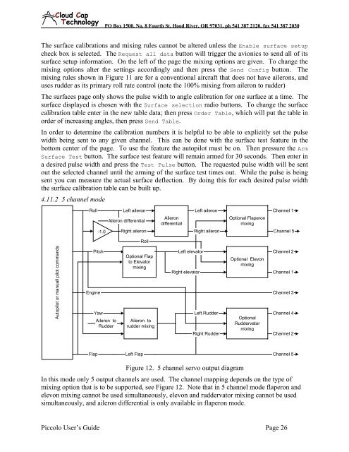
4.11.2 5 channel mode<br />
Roll<br />
Left aileron<br />
Aileron differential<br />
Aileron<br />
differential<br />
Left aileron<br />
Optional Flaperon<br />
mixing<br />
Channel 1<br />
-1.0<br />
Right aileron<br />
Right aileron<br />
Channel 5<br />
Roll<br />
Autopilot or manuall pilot commands<br />
Pitch<br />
Right elevator<br />
Optional Elevon<br />
mixing<br />
Channel 2<br />
Channel 1<br />
Engine Channel 3<br />
Yaw<br />
Aileron to<br />
Rudder<br />
Optional Flap<br />
to Elevator<br />
mixing<br />
Aileron to<br />
rudder mixing<br />
Left elevator<br />
Left Rudder<br />
Right Rudder<br />
Optional<br />
Ruddervator<br />
mixing<br />
Channel 4<br />
Channel 2<br />
Flap Left Flap Channel 5<br />
Figure 12. 5 channel servo output diagram<br />
In this mode only 5 output channels are used. The channel mapping depends on the type of<br />
mixing option that is to be supported, see Figure 12. Note that in 5 channel mode flaperon and<br />
elevon mixing cannot be used simultaneously, elevon and ruddervator mixing cannot be used<br />
simultaneously, and aileron differential is only available in flaperon mode.<br />
<strong>Piccolo</strong> User’s Guide Page 26