Piccolo system user guide - Unmanned Aircraft & Drones
Piccolo system user guide - Unmanned Aircraft & Drones
Piccolo system user guide - Unmanned Aircraft & Drones

You also want an ePaper? Increase the reach of your titles
YUMPU automatically turns print PDFs into web optimized ePapers that Google loves.
Clo ud Cap<br />
Technology<br />
PO Box 1500, No. 8 Fourth St, Hood River, OR 97031, ph 541 387 2120, fax 541 387 2030<br />
4.3 Ground station screen<br />
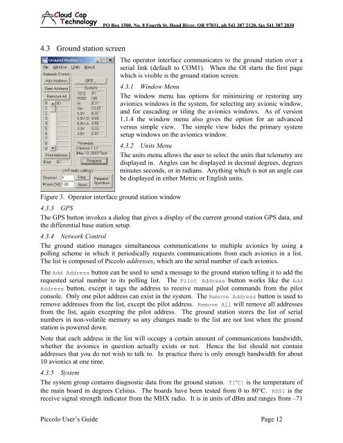
Figure 3. Operator interface ground station window<br />
The operator interface communicates to the ground station over a<br />
serial link (default to COM1). When the OI starts the first page<br />
which is visible is the ground station screen.<br />
4.3.1 Window Menu<br />
The window menu has options for minimizing or restoring any<br />
avionics windows in the <strong>system</strong>, for selecting any avionic window,<br />
and for cascading or tiling the avionics windows. As of version<br />
1.1.4 the window menu also gives the option for an advanced<br />
versus simple view. The simple view hides the primary <strong>system</strong><br />
setup windows on the avionics window.<br />
4.3.2 Units Menu<br />
The units menu allows the <strong>user</strong> to select the units that telemetry are<br />
displayed in. Angles can be displayed in decimal degrees, degrees<br />
minutes seconds, or in radians. Anything which is not an angle can<br />
be displayed in either Metric or English units.<br />
4.3.3 GPS<br />
The GPS button invokes a dialog that gives a display of the current ground station GPS data, and<br />
the differential base station setup.<br />
4.3.4 Network Control<br />
The ground station manages simultaneous communications to multiple avionics by using a<br />
polling scheme in which it periodically requests communications from each avionics in a list.<br />
The list is composed of <strong>Piccolo</strong> addresses, which are the serial number of each avionics.<br />
The Add Address button can be used to send a message to the ground station telling it to add the<br />
requested serial number to its polling list. The Pilot Address button works like the Add<br />
Address button, except it tags the address to receive manual pilot commands from the pilot<br />
console. Only one pilot address can exist in the <strong>system</strong>. The Remove Address button is used to<br />
remove addresses from the list, except the pilot address. Remove All will remove all addresses<br />
from the list, again excepting the pilot address. The ground station stores the list of serial<br />
numbers in non-volatile memory so any changes made to the list are not lost when the ground<br />
station is powered down.<br />
Note that each address in the list will occupy a certain amount of communications bandwidth,<br />
whether the avionics in question actually exists or not. Hence the list should not contain<br />
addresses that you do not wish to talk to. In practice there is only enough bandwidth for about<br />
10 avionics at one time.<br />
4.3.5 System<br />
The <strong>system</strong> group contains diagnostic data from the ground station. T[°C] is the temperature of<br />
the main board in degrees Celsius. The boards have been tested from 0 to 80°C. RSSI is the<br />
receive signal strength indicator from the MHX radio. It is in units of dBm and ranges from –71<br />
<strong>Piccolo</strong> User’s Guide Page 12