Piccolo system user guide - Unmanned Aircraft & Drones
Piccolo system user guide - Unmanned Aircraft & Drones
Piccolo system user guide - Unmanned Aircraft & Drones

You also want an ePaper? Increase the reach of your titles
YUMPU automatically turns print PDFs into web optimized ePapers that Google loves.
Clo ud Cap<br />
Technology<br />
PO Box 1500, No. 8 Fourth St, Hood River, OR 97031, ph 541 387 2120, fax 541 387 2030<br />
To see the flight plans that are onboard the avionics press the Request button. This will trigger<br />
the avionics to send all of its flight plans.<br />
4.7.1 All about flight plans<br />
Flight plans are made of linked lists of waypoints. Each waypoint encodes latitude, longitude,<br />
altitude, and the index of the next waypoint to be used. The avionics has storage for 100<br />
waypoints. These waypoints can be used to make one flight plan that is 100 waypoints long, or<br />
50 flight plans with two waypoints each, or any combination between. The key concept is that<br />
all flight plans must close. This means that at some point the next waypoint must point to a<br />
waypoint that was previously in the list. In Figure 6 the flight plan is made of waypoint 10,<br />
which goes to 11, which goes to 12, to 13, to 14, to 15, to 16, and back to 14. Note that although<br />
all flight plans must close, they do not have to be a loop. In the sequence given above the<br />
aircraft will end up flying the triangle between waypoints 14, 15 and 16.<br />
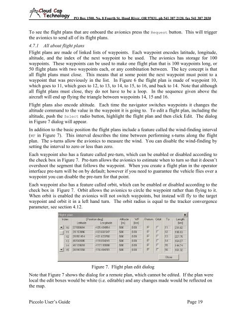
Flight plans also encode altitude. Each time the navigator switches waypoints it changes the<br />
altitude command to the value in the waypoint it is going to. To edit a flight plan, including the<br />
altitude, push the Select radio button, highlight the flight plan and then click Edit. The dialog<br />
in Figure 7 dialog will appear.<br />
In addition to the basic position the flight plans include a feature called the wind-finding interval<br />
(WF in Figure 7). This interval describes the time between performing s-turns along the flight<br />
plan. The s-turns allow the avionics to measure the wind. You can disable the wind-finding by<br />
setting the interval to zero or less than zero.<br />
Each waypoint also has a feature called pre-turn, which can be enabled or disabled according to<br />
the check box in Figure 7. Pre-turn allows the avionics to estimate when to turn so that it doesn’t<br />
overshoot the segment that follows the waypoint. When you create a flight plan in the operator<br />
interface pre-turn will be on by default; however if you need to guarantee the vehicle flies over a<br />
waypoint you can disable the pre-turn for that point.<br />
Each waypoint also has a feature called orbit, which can be enabled or disabled according to the<br />
check box in Figure 7. Orbit allows the avionics to circle the waypoint rather than flying to it.<br />
When orbit is enabled the avionics will not switch waypoints, but instead will fly to the target<br />
waypoint and orbit it in a left hand turn. The orbit radius is equal to the tracker convergence<br />
parameter, see section 4.12.<br />
Figure 7. Flight plan edit dialog<br />
Note that Figure 7 shows the dialog for a remote plan, which cannot be edited. If the plan were<br />
local the edit boxes would be white (i.e. editable) and any changes made would be reflected on<br />
the map.<br />
<strong>Piccolo</strong> User’s Guide Page 19