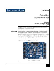
iSTAR Pro 4U Rack Mount Quick Start Installation Guide
iSTAR Pro 4U Rack Mount Quick Start Installation Guide
iSTAR Pro 4U Rack Mount Quick Start Installation Guide

You also want an ePaper? Increase the reach of your titles
YUMPU automatically turns print PDFs into web optimized ePapers that Google loves.
Components/Connections<br />
Bottom Row Rear Connectors<br />
Doors 9-16 and Inputs 21-32 are on the bottom connector.<br />
The Fire Alarm input (FA/NO) on the IN31-32 connector is a Normally Open (NO) dry<br />
connection. When the connection closes, it indicates an external Fire Alarm is active. If<br />
an APD8 jumper is set to position D, the lock power for that lock will be inhibited. See<br />
Figure 19 for more details. The Fire Alarm will also be indicated on the front panel and<br />
can be wired to an input and used to create an event in the C•CURE system. See page12.<br />
Tied to Door 8<br />
on ACM 1<br />
Tied to Door 16<br />
on ACM 2<br />
Set ACM S1-1 to OFF<br />
when RM8/16 are used<br />
FIGURE 7. Bottom Row Rear Connectors - <strong>4U</strong> RM <strong>Rack</strong> <strong>Mount</strong> ISTAR<br />
Adding I/8 or R/8 Bus Modules<br />
It is possible to wire bus modules on the same lines as Doors 1-16, observing normal<br />
RS-485 termination rules.<br />
Another option is to use the RM BUS connector. The RM BUS connector has two RM<br />
Bus connections which can be used to wire I/8 and R/8 bus modules.<br />
RM 8 and DR 8 are connected to STAR1 on the first ACM. RM 16 and DR 16 are<br />
connected to STAR1 on the second ACM.<br />
15