Video and Image Processing Up Conversion Example Design
Video and Image Processing Up Conversion Example Design
Video and Image Processing Up Conversion Example Design

You also want an ePaper? Increase the reach of your titles
YUMPU automatically turns print PDFs into web optimized ePapers that Google loves.
Functional Description<br />
The external memory is a double data rate (DDR) RAM in the example<br />
design, <strong>and</strong> is accessed via SOPC Builder arbitration logic as shown in<br />
Figure 9. SOPC Builder is responsible for sharing access time to the DDR<br />
between the frame buffer block <strong>and</strong> other blocks in the design. The block<br />
includes a writer, which writes the input stream into one of the buffers,<br />
<strong>and</strong> a reader, which reads the output stream from another (never the<br />
same) buffer. There is always one buffer which is neither being written to<br />
nor read from. This "spare" buffer is required to allow the input <strong>and</strong><br />
output to run at differing frame rates.<br />
The frame buffer operates by swapping frames according to the following<br />
algorithms.<br />
Each time the input finishes writing a frame of data into a buffer:<br />
Wait until the spare buffer has data that has already been displayed,<br />
then start writing the next input frame into the spare buffer. The<br />
buffer just written into then becomes the new spare buffer. No frame<br />
is dropped in this configuration.<br />
Each time the output finishes reading a frame of data from a buffer:<br />
If the spare buffer has data which has not yet been displayed then<br />
start reading the next output frame from the spare buffer. The frame<br />
buffer just read from then becomes the new spare buffer. Otherwise,<br />
start reading the next output frame from the same buffer (a frame is<br />
repeated).<br />
VGA Output<br />
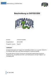
Figure 10 shows a simple block diagram of the VGA Output component.<br />
Figure 10. VGA Output Component<br />
Ready<br />
Valid<br />
Data<br />
24<br />
SOPC System Clock<br />
(130 MHz)<br />
Dual-Clock FIFO<br />
VGA Clock<br />
(65 MHz)<br />
VGA Syncs<br />
Generator<br />
R<br />
G<br />
B<br />
Syncs<br />
The VGA Output is an SOPC Builder component written in Verilog HDL.<br />
The source code can be found in the directory \vga_output.<br />
Altera Corporation 13<br />
Preliminary