ULN-2550 User Manual - Jackson Labs Technologies, Inc.
ULN-2550 User Manual - Jackson Labs Technologies, Inc.
ULN-2550 User Manual - Jackson Labs Technologies, Inc.
You also want an ePaper? Increase the reach of your titles
YUMPU automatically turns print PDFs into web optimized ePapers that Google loves.
<strong>ULN</strong>-<strong>2550</strong> <strong>User</strong> <strong>Manual</strong><br />
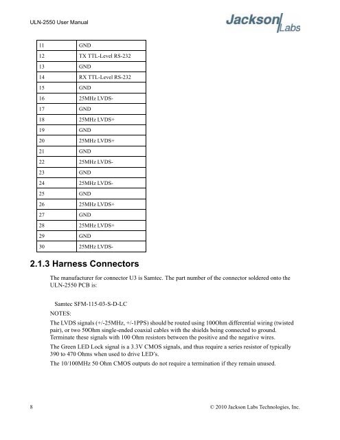
11 GND<br />
12 TX TTL-Level RS-232<br />
13 GND<br />
14 RX TTL-Level RS-232<br />
15 GND<br />
16 25MHz LVDS-<br />
17 GND<br />
18 25MHz LVDS+<br />
19 GND<br />
20 25MHz LVDS+<br />
21 GND<br />
22 25MHz LVDS-<br />
23 GND<br />
24 25MHz LVDS-<br />
25 GND<br />
26 25MHz LVDS+<br />
27 GND<br />
28 25MHz LVDS+<br />
29 GND<br />
30 25MHz LVDS-<br />
2.1.3 Harness Connectors<br />
The manufacturer for connector U3 is Samtec. The part number of the connector soldered onto the<br />
<strong>ULN</strong>-<strong>2550</strong> PCB is:<br />
Samtec SFM-115-03-S-D-LC<br />
NOTES:<br />
The LVDS signals (+/-25MHz, +/-1PPS) should be routed using 100Ohm differential wiring (twisted<br />
pair), or two 50Ohm single-ended coaxial cables with the shields being connected to ground.<br />
Terminate these signals with 100 Ohm resistors between the positive and the negative wires.<br />
The Green LED Lock signal is a 3.3V CMOS signals, and thus require a series resistor of typically<br />
390 to 470 Ohms when used to drive LED’s.<br />
The 10/100MHz 50 Ohm CMOS outputs do not require a termination if they remain unused.<br />
8 © 2010 <strong>Jackson</strong> <strong>Labs</strong> <strong>Technologies</strong>, <strong>Inc</strong>.


