ULN-2550 User Manual - Jackson Labs Technologies, Inc.
ULN-2550 User Manual - Jackson Labs Technologies, Inc.
ULN-2550 User Manual - Jackson Labs Technologies, Inc.
You also want an ePaper? Increase the reach of your titles
YUMPU automatically turns print PDFs into web optimized ePapers that Google loves.
<strong>ULN</strong>-<strong>2550</strong> <strong>User</strong> <strong>Manual</strong><br />
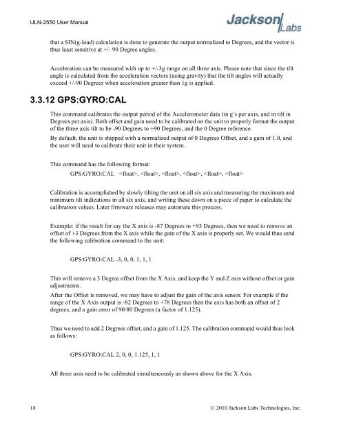
that a SIN(g-load) calculation is done to generate the output normalized to Degrees, and the vector is<br />
thus least sensitive at +/- 90 Degree angles.<br />
Acceleration can be measured with up to +/-3g range on all three axis. Please note that since the tilt<br />
angle is calculated from the acceleration vectors (using gravity) that the tilt angles will actually<br />
exceed +/-90 Degrees when acceleration greater than 1g is applied.<br />
3.3.12 GPS:GYRO:CAL<br />
This command calibrates the output period of the Accelerometer data (in g’s per axis, and in tilt in<br />
Degrees per axis). Both offset and gain need to be calibrated on the unit to properly format the output<br />
of the three axis tilt to be -90 Degrees to +90 Degrees, and the 0 Degree reference.<br />
By default, the unit is shipped with a normalized output of 0 Degrees Offset, and a gain of 1.0, and<br />
the user will need to calibrate their unit in their system.<br />
This command has the following format:<br />
GPS:GYRO:CAL , , , , , <br />
Calibration is accomplished by slowly tilting the unit on all six axis and measuring the maximum and<br />
minimum tilt indications in all six axis, and writing these down on a piece of paper to calculate the<br />
calibration values. Later firmware releases may automate this process.<br />
Example: if the result for say the X axis is -87 Degrees to +93 Degrees, then we need to remove an<br />
offset of +3 Degrees from the X axis while the gain of the X axis is properly set. We would thus send<br />
the following calibration command to the unit:<br />
GPS:GYRO:CAL -3, 0, 0, 1, 1, 1<br />
This will remove a 3 Degree offset from the X Axis, and keep the Y and Z axis without offset or gain<br />
adjustments.<br />
After the Offset is removed, we may have to adjust the gain of the axis sensor. For example if the<br />
range of the X Axis output is -82 Degrees to +78 Degrees then the axis has both an offset of 2<br />
degrees, and a gain error of 90/80 Degrees (a factor of 1.125).<br />
Thus we need to add 2 Degrees offset, and a gain of 1.125. The calibration command would thus look<br />
as follows:<br />
GPS:GYRO:CAL 2, 0, 0, 1.125, 1, 1<br />
All three axis need to be calibrated simultaneously as shown above for the X Axis.<br />
18 © 2010 <strong>Jackson</strong> <strong>Labs</strong> <strong>Technologies</strong>, <strong>Inc</strong>.


