ULN-2550 User Manual - Jackson Labs Technologies, Inc.
ULN-2550 User Manual - Jackson Labs Technologies, Inc.
ULN-2550 User Manual - Jackson Labs Technologies, Inc.
You also want an ePaper? Increase the reach of your titles
YUMPU automatically turns print PDFs into web optimized ePapers that Google loves.
<strong>ULN</strong>-<strong>2550</strong> <strong>User</strong> <strong>Manual</strong><br />
2Quick-Start<br />
Instructions<br />
2.1 Powering Up the Unit<br />
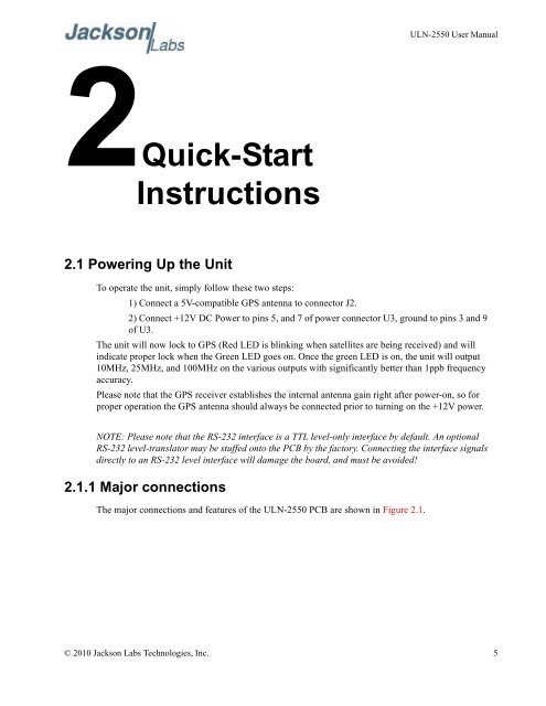
To operate the unit, simply follow these two steps:<br />
1) Connect a 5V-compatible GPS antenna to connector J2.<br />
2) Connect +12V DC Power to pins 5, and 7 of power connector U3, ground to pins 3 and 9<br />
of U3.<br />
The unit will now lock to GPS (Red LED is blinking when satellites are being received) and will<br />
indicate proper lock when the Green LED goes on. Once the green LED is on, the unit will output<br />
10MHz, 25MHz, and 100MHz on the various outputs with significantly better than 1ppb frequency<br />
accuracy.<br />
Please note that the GPS receiver establishes the internal antenna gain right after power-on, so for<br />
proper operation the GPS antenna should always be connected prior to turning on the +12V power.<br />
NOTE: Please note that the RS-232 interface is a TTL level-only interface by default. An optional<br />
RS-232 level-translator may be stuffed onto the PCB by the factory. Connecting the interface signals<br />
directly to an RS-232 level interface will damage the board, and must be avoided!<br />
2.1.1 Major connections<br />
The major connections and features of the <strong>ULN</strong>-<strong>2550</strong> PCB are shown in Figure 2.1.<br />
© 2010 <strong>Jackson</strong> <strong>Labs</strong> <strong>Technologies</strong>, <strong>Inc</strong>. 5


