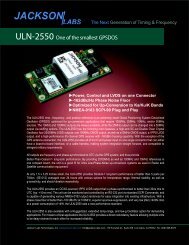
ULN-2550 User Manual - Jackson Labs Technologies, Inc.
ULN-2550 User Manual - Jackson Labs Technologies, Inc.
ULN-2550 User Manual - Jackson Labs Technologies, Inc.

Create successful ePaper yourself
Turn your PDF publications into a flip-book with our unique Google optimized e-Paper software.
<strong>ULN</strong>-<strong>2550</strong> <strong>User</strong> <strong>Manual</strong><br />
2.3.1 “Help” and command overview<br />
• A listing of the available RS-232 commands can be shown by typing "help"<br />
• "*IDN" can be used to see if the connection works. Both commands need to be followed by<br />
pressing “Enter”<br />
2.3.2 Loop parameter adjustment<br />
• All loop parameters can be controlled via the RS-232 serial port.<br />
• Loop parameters are optimized for the OCXO on the board, and changing the factory settings may<br />
result in the unit’s performance to deteriorate.<br />
The commands to control the loop parameters are part of the servo command. See also the SERVO<br />
Subsystem section below.<br />
The individual commands are:<br />
EFC Scale: this is the proportional gain of the PID loop. Higher values will give quicker<br />
convergence, and faster locking of the GPS time (lower loop time constant), lower values give less<br />
noise. Values between 0.7 (good double oven OCXO) and 6.0 (simple single-oven OCXO) are<br />
typical.<br />
EFC Damping: overall IIR filter time constant. higher values increase loop time constant. <strong>Jackson</strong><br />
<strong>Labs</strong> <strong>Technologies</strong>, <strong>Inc</strong>. typically uses values between 10 to 50. Setting this value too high may cause<br />
loop instability.<br />
Phase compensation: this is the Integral part of the PID loop. This corrects phase offsets between<br />
the <strong>ULN</strong>-<strong>2550</strong> 1PPS signal and the UTC 1PPS signal as generated by the GPS receiver. Set higher<br />
values for tighter phase-following at the expense of frequency stability. Typical values range from 4<br />
- 30, 25 being the default. Setting this value too high may cause loop instability.<br />
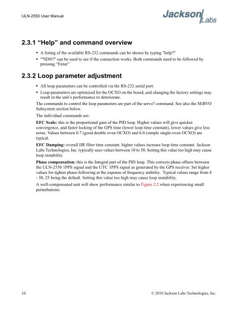
A well-compensated unit will show performance similar to Figure 2.2 when experiencing small<br />
perturbations:<br />
10 © 2010 <strong>Jackson</strong> <strong>Labs</strong> <strong>Technologies</strong>, <strong>Inc</strong>.