Magnetic Fields and Magnetic Diagnostics for Tokamak Plasmas
Magnetic Fields and Magnetic Diagnostics for Tokamak Plasmas
Magnetic Fields and Magnetic Diagnostics for Tokamak Plasmas

You also want an ePaper? Increase the reach of your titles
YUMPU automatically turns print PDFs into web optimized ePapers that Google loves.
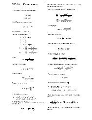
<strong>Magnetic</strong> fields <strong>and</strong> tokamak plasmas<br />
Alan Wootton<br />
plasma<br />
diamagnetic loop<br />
integrator gate<br />
compensating coil<br />
•<br />
•<br />
Ω<br />
balance resistor<br />
C<br />
Ω i<br />
Ci<br />
_<br />
Figure 14.5. A diamagnetic coil compensating system<br />
An alternative technique is to wrap two simple toroidal flux loops around the vessel, but at<br />
different minor radii. Such a configuration is shown in Figure 14.4. Let two concentric loops<br />
have radii b 1 <strong>and</strong> b 2 , <strong>and</strong> let R l be the major radius of the loops. Then, remembering that B φe =<br />
B φ0 R l /R, we have after time integration<br />
⎡<br />
Φ(b i<br />
) = 2πR l<br />
B φ0<br />
R l<br />
− R 2 2<br />
⎢<br />
l<br />
− b i<br />
⎣<br />
( ) 1 2<br />
⎡<br />
Φ(b i<br />
) = 2πR l<br />
B φ0<br />
R l<br />
− R 2 2<br />
⎢<br />
l<br />
− b i<br />
⎣<br />
( ) 1 2<br />
⎤<br />
⎥ +δΦ 14.24<br />
⎦<br />
⎤<br />
⎥ +δΦ 14.25<br />
⎦<br />
δΦ = Φ(b 1<br />
) − k( Φ(b 2<br />
) − Φ(b 1<br />
)); k =<br />
b 1<br />
2<br />
b 2 2 − b 1<br />
2<br />
R<br />
l<br />
2<br />
− b 12<br />
+ R 2 2<br />
− b 2<br />
R l<br />
+<br />
R 2 2<br />
+ b<br />
l 1<br />
l<br />
14.26<br />
111