Magnetic Fields and Magnetic Diagnostics for Tokamak Plasmas
Magnetic Fields and Magnetic Diagnostics for Tokamak Plasmas
Magnetic Fields and Magnetic Diagnostics for Tokamak Plasmas

Create successful ePaper yourself
Turn your PDF publications into a flip-book with our unique Google optimized e-Paper software.
<strong>Magnetic</strong> fields <strong>and</strong> tokamak plasmas<br />
Alan Wootton<br />
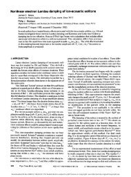
Figure 19.2. The currents flowing in a vessel or shell with toroidal<br />
(i.e. longitudinal) <strong>and</strong> poloidal (i.e. transverse) gaps.<br />
There are two types of insulating breaks, as shown in Figure 19.1 <strong>and</strong> Figure 19.2, (taken from<br />
Mukhovatov <strong>and</strong> Shafranov). For transverse gaps (Figure 19.1) any symmetric component of<br />
current must flow on the vessel surfaces. However, non symmetric components, introduced <strong>for</strong><br />
example by axisymmetric plasma motion, will produce volume currents. At the gap the non<br />
symmetric currents flow in opposite directions. They will produce a local vertical field, which<br />
must affect the plasma position, as well as the interpretation of magnetic coil signals. The two<br />
(surface <strong>and</strong> bulk) currents have different decay times, as discussed later.<br />
If both a transverse <strong>and</strong> a longitudinal gap exists, Figure 19.2 shows that <strong>for</strong> the non symmetric<br />
components the placing of the break in poloidal angle is important. A longitudinal gap at the<br />
outer equator does not distort the field, while a gap at the top or bottom does.<br />
x<br />
d<br />
a<br />
b<br />
z<br />
Figure 19.3. The geometry of a conducting shell or vessel.<br />
We are concerned with the currents induced in a resistive vacuum vessel lying outside the<br />
plasma, <strong>and</strong> their effects on all the measurements we have discussed. As a characteristic<br />
example, consider a homogeneous field B = B 0 sin(ωt) parallel to the plane of a conducting plate;<br />
the inner <strong>and</strong> outer boundaries of the plate are at a distance b <strong>and</strong> a from the symmetry plane (see<br />
Figure 19.3). Maxwell's equations reduce to<br />
∇ × ( ∇ × B) = −µ 0<br />
σ ∂B<br />
∂t<br />
19.1<br />
When the ratio of the plate thickness to the layer thickness is much less than unity, i.e. d/b > d skin , (i.e. at high frequency) we have a thick plate, <strong>and</strong> we can consider<br />
141