Magnetic Fields and Magnetic Diagnostics for Tokamak Plasmas
Magnetic Fields and Magnetic Diagnostics for Tokamak Plasmas
Magnetic Fields and Magnetic Diagnostics for Tokamak Plasmas

You also want an ePaper? Increase the reach of your titles
YUMPU automatically turns print PDFs into web optimized ePapers that Google loves.
<strong>Magnetic</strong> fields <strong>and</strong> tokamak plasmas<br />
Alan Wootton<br />
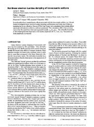
Figure 20.3. The geometry of an iron core <strong>and</strong><br />
a linked plasma of current I. The contour l<br />
considered in the text is shown.<br />
Now consider the case shown in Figure 20.3, an iron core with a central limb as on TEXT. If the<br />
total number of turns linking the center core is 0, <strong>and</strong> there is no current in the iron (Equation<br />
20.4) then ∫H . dl = 0 <strong>for</strong> any contour l inside the iron. Then H derives still from a single<br />
potential, <strong>and</strong> all our previous steps are valid. However, if a finite number of amp turns I links<br />
the iron, then ∫H . dl = I. This means that we can still write the field in the iron as ∇Φ, but now Φ<br />
is multi valued, increasing by ±I once around the contour l. That is, in this case, Equations 20.8<br />
<strong>and</strong> 20.9 apply in the iron, but with the additional constraint<br />
∫ ∇Φ • dl = I<br />
20.10<br />
l<br />
In this case, had we assumed perpendicularity, we would have obtained ∫H . dl = 0, while in reality<br />
∫H . dl = I. Thus the field lines only enter the iron core perpendicularly if no current flows in the<br />
iron, <strong>and</strong> the net ampere turns is zero.<br />
The only place that the iron really affects magnetic diagnostics is in the equilibrium<br />
reconstruction. No longer can we use the free space expressions <strong>for</strong> a circular current filament,<br />
but they must be modified to satisfy the boundary condition. In toroidal plasma devices we<br />
almost always satisfy the conditions necessary <strong>for</strong> the boundary condition Equation 20.7. One<br />
way to model the effect of iron is by placing additional circular filaments inside the iron itself,<br />
with currents chosen to satisfy Equation 20.7 at a given number of locations. This is illustrated<br />
in Figure 20.4: the 'image" filaments must have a current flowing in the same direction as the<br />
filament in air, so that there is an attraction between the filament in air <strong>and</strong> the iron itself. As the<br />
filament in air gets closer to the iron, the "image" current must increase, <strong>and</strong> so the attraction<br />
must increase. This means that an iron core can lead to an axisymmetric, or n = 0, instability.<br />
146